Chromatic Dispersion Challenges —
With the speed of networks continuously increasing, the impact of optical dispersion becomes the largest impairment in migrating to higher speeds. Understanding chromatic dispersion (CD) of an optical fiber is critical for those looking to migrate to 40 Gb/s or higher speeds. In this article we review what CD is and how its effects can be mitigated.
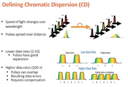
Optical dispersion is the spreading of an optical pulse as it travels along a fiber. The effects of dispersion accumulate with distance, and can limit how far a signal can be transmitted through a fiber without affecting signal quality. Once the spreading of the pulses starts to overlap, the signal quality decreases. Designers must consider the effects of optical dispersion when upgrading to higher speeds or longer distances. (See Figure 1.)
Figure 1. The faster the transmission rate the greater the effects of chromatic dispersion. (Courtesy Fiber Insight)
Chromatic dispersion is actually the sum of 2 things: material dispersion and waveguide dispersion.
Material dispersion occurs because the speed of light varies at different wavelengths through glass. Fiber manufacturers optimize their fibers for minimizing this effect at specific wavelengths. In addition, because a pulse of light has some spectral width, each of its wavelengths will travel at different speeds within the fiber. The narrower the laser’s pulse width, the smaller the effect of chromatic dispersion.
Chromatic dispersion occurs in single-mode fibers because the different wavelengths being transmitted by the laser have different propagation times through the fiber. For example, a Fabry-Perot (FP) laser with a center wavelength of 1310 nanometers (nm) having a spectral width of 4 nm, actually transmits between 1308 nm and 1312 nm. Therefore, the difference in the speed of light between these wavelengths causes the pulse to spread.
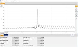
One method to decrease the effects of material dispersion is to use the narrower spectral width distributed feedback (DFB) laser, which is typically less than 1 nm in spectral width. This is ideal for use in Dense Wavelength Division Multiplexed (DWDM) systems which require tight wavelength channel separation. (See Figure 2.)
Figure 2. A narrow spectral width DFB laser profile used in high speed systems to minimize chromatic dispersion. (Courtesy EXFO, Inc.)
The second type of optical dispersion is called waveguide dispersion. It is caused because light is being transmitted in the fiber’s mode-field diameter (MFD), which includes the fiber core and the inner part of the cladding. As the speed of light is defined by its Index of Refraction (I.R.), the difference in the I.R. of the core and cladding causes the pulse to spread.
Material dispersion and waveguide dispersion will cancel each other out at certain wavelengths, forming a zero-dispersion point. In standard ITU-T G.652 single-mode fiber, which is optimized for 1310 nm, material and waveguide dispersion cancel near 1310 nanometers. Dispersion shifting moves the zero-dispersion point to longer wavelengths, which have lower attenuation, thus increasing distances between regenerators. These fibers specified by the ITU-T as G.654 and G.655 are ideal for DWDM, long haul, and use with optical amplifiers.
Now that we’ve covered the basics of CD, our next article will address options for how manufacturers mitigate the effects of chromatic dispersion.
About the Author


