Evaluating the Options —
For any cellular amplification system installation, the cabling is a major factor influencing the signal strength and improvements in cellular coverage inside a building. There are primarily 3 categories of cable used in systems that amplify indoor cellular signal: coax, category twisted pair, and fiber. Each has its own purpose and each needs to be used strategically for an efficient design that provides a facility with optimum amplification at the best cost.
Coax Cable
For in-building cellular amplification systems, coax cables transmit analog signal between a signal source, such as a donor antenna on the roof of the building, and the headend of the system. It can also be used to transmit the signal from the radios to the antennas that distribute the signal to building occupants. One strategic way to do this is by placing redistribution equipment (equipment that converts the analog signal to a digital form) nearby to minimize the negative effects of coax for stronger transmission.
InvisiLight® Solution for Deploying Fiber
April 2, 2022Go to Market Faster. Speed up Network Deployment
April 2, 2022Episode 10: Fiber Optic Closure Specs Explained…
April 1, 2022Food for Thought from Our 2022 ICT Visionaries
April 1, 2022While coax cables are an essential element in most in-building cellular amplification systems, they do have drawbacks.
• Power is lost over these cables on all runs due to simple physics, but the loss drastically increases over longer runs. For example, over 100 feet half the power or more may be lost.
• Also, twice as much power is lost when transmitting at higher frequencies than in the lower frequencies, so a system designer must take into consideration the frequency bands that will be amplified. High bands (1700-5000 MHz) may lose 3-6dB (50%-75%) per 100 linear feet. Low bands (600-800 MHz) might lose 1.5-2dB per 100 linear feet.
• The amount of power that reaches the antenna directly impacts the coverage footprint and the user experience.
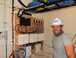
Headend of the School. 3 Network Units: 1 for each building, and 2 coverage units feeding service. (Pictured with Taylor Underwood)
Of the 3 types of cables used, coax is the most challenging to install. If connectors are installed poorly or if there are breaks in the cable, there can be passive intermodulation which is a phenomenon where multiple frequencies mix together resulting in spurious harmonics, interference, and unintended leakage of power and signal.
While sweep tests should be done on all cable installations to ensure that specifications and
standards are met, the tests for coax cable are the most complex and time-consuming.
• Because coax transmits analog signals, there are more characteristics to test, such as different frequency ranges for the standards required by each of the carrier’s bands. The test might pass at lower bands but can fail on a high band. Field technicians would then need to troubleshoot to find the root cause of the failure. This may require reinstalling and/or cleaning connectors multiple times due to simple things like oils from the installer’s hands left on the connectors, slight condensation, or miniscule metal shavings or dirt and dust from when the cable was cut and prepped.
• Coax cables are also thick and harder to install when tight radiuses are required, so crimping can become an issue which results in a test fail.
The average price of half inch coax is $1.50-$2.00 per foot. Each connector costs $25-$50 to replace. A coaxial sweep analyzer costs $10-$20K or more. (Based on pricing quotes from major vendors Anixter and/or Anritsu.)
Category Cable
Category 6 twisted pair cable can be used to transmit signal from the headend of the system to the remote radios and antennas. There are many advantages to using Category versus Coax cable.
• Category cable is all digital so there is no signal degradation up to 300 linear feet or 600 feet with a cable extender.
• Unlike coax, it is simple and foolproof to put a network connector on the end of category cable; the installer simply needs to ensure that the 8 wires are in the correct positions before crimping.
• It is also thinner cable with a smaller bend radius so it can be installed in tight areas.
• Simple and quick tests are done to make sure the cable conforms to standards for data rate over the length using an inexpensive Fluke meter or similar device. If the test fails, the installer can usually just snip off a connector and replace it, taking only a couple of minutes.
• Care must be taken when bundling category cable runs as this can cause too much noise from other cables in the bundle and can cause errors in the digital system.
The average price for Category 6 cable is $.50-$.60 per foot. Each connector costs $.50 to replace. A Fluke meter for testing costs $500 to $750. (Based on pricing quotes from major vendors Anixter and/or Anritsu.)
Outdoor Donor Antennas
Fiber
• Similar to Category 6 twisted pair cable, fiber is all-digital but it doesn’t have the same distance limitations. With single mode fiber, runs cans transmit anywhere from a few hundred feet upwards of 25 miles depending on the amplifiers from the headend to the remote radios/antennas inside the building — without needing any additional repeaters or hardware transceivers.
• Also, there are different ways fiber can be modulated for greater signal capacity than category cable, so capacity and radio frequency (RF) propagation planning should be done as part of an in-building system design to determine the optimum cabling to install.
• Inside fiber cables, the signal is transmitted over pristine glass that is very sensitive. It requires minimal back reflection which can cause the light to go in the wrong direction.
• It also requires correct polarizations, which is the angle the light is reflecting throughout the cable. If the light is not bouncing at the right angles, then there can be lost signal.
• These factors make the installation more delicate as harsh bends and improper connector surfaces need to be avoided.
• Splicing the connectors on the ends also requires specific expertise and more expensive equipment, such as a fusion splicer that "welds" glass together without significant imperfections.
• Since fiber cables are tiny, dust particles can cause unwanted loss as well.
Fiber used for in-building distributed antenna systems (DAS) normally costs $2.00-$8.00+ per linear foot. (Based on pricing quotes from major vendors Anixter and/or Anritsu.)
Alternative Solution
Due to the technical limitations on the length of category and coax cable runs, larger facilities looking to improve cellular reception for occupants, IoT, or cellular devices have historically deployed expensive DAS with long fiber runs throughout the buildings.
However, traditional DAS solutions are not always financially viable for most facilities under a million square feet. This is due to the high upfront cost of equipment and cabling, extensive length
of installation time and contract negotiations with carriers, and extra operating expenses due to the heat, electrical, and air conditioning loads.
M S Benbow & Associates (MSB) has found a more cost-effective solution, using all 3 types of cabling, for providing cellular amplification in multi-building complexes, skyscrapers, and other larger facilities.
One application example illustrates the point well. Using Cel-Fi QUATRA, an active DAS hybrid from Nextivity, MSB amplified cellular signal throughout a 3-building, new construction, K-6 school with 236,000 square feet of indoor space. The entire system, including installation, cost the school about the same as it would have cost for only a headend of a traditional DAS.
The system is fully digital and uses both category and coax cable to deliver up to 100dB gain simultaneously on multiple carrier networks. A recent Fiber HUB addition to the hybrid allows fiber runs to transmit signal in multi-building and larger facilities from the headend of the system to the remote units at distances of up to 1.25 miles.
The hybrid solution can be deployed with an off-air donor signal or connected to a small cell to create a distributed small cell network called a Supercell. When deployed off-air, donor antennas are generally placed on the roof of a facility, one for each carrier. Coax is run from the donor antennas to the system headend. From the headend, category cable is run up to a maximum of 656 horizontal or vertical feet (with signal extenders) to the remote units inside the facility that distribute the signal to occupants. The Fiber HUB and fiber runs are used when longer runs are needed.
We found the Fiber HUB fit into the infrastructure like traditional DAS but without being traditional DAS. The Fiber HUB enabled the company to provide cell service to multiple and larger buildings, all while cutting down on the infrastructure costs.
Interestingly, the entire school was constructed as a LEED-certified building, so it was a giant Faraday cage with no cellular signal coming in or out. Outside there was a fairly decent signal, but inside all the materials were RF-blocking, resulting in no signal.
• The headend of the hybrid was placed in the 2-story main building.
• 4 antennas were put on the roof of the main building, 1 for each carrier, with coax cable run to the headend to provide the signal source for delivering cellular coverage to the entire school campus.
• 6 strands of single mode fiber were run 700 feet from the headend to Fiber HUBs in the other 2 buildings.
• The fiber was cut and spliced at key points, so it went back and forth between the buildings, providing full redundancy with a couple of backups and an alternate route if needed.
• Cat 6A cable was run from the headend in the main building and the Fiber HUBs in the 2 external buildings to the 6 remote units positioned inside each of the 3 buildings.
It took 2 of our engineers about a week to get everything turned up and checked out, including the cables, antennas, and sweep testing. It took an hour to commission the system. The system can monitor itself for any type of interference that is introduced into the system, and it has an online portal and apps for remote performance monitoring, which is important to us in providing maintenance and ensuring that standards promised are met.
For more information, please email [email protected] or visit https://www.msbenbow.com/. Follow M S Benbow on Linkedin: https://www.linkedin.com/company/msbenbow/.
