Legacy Fibers in a 5G World
5G communications systems require reliable single-mode fiber connectivity. In this article I address challenges in the physical plant that deal with new installations and legacy networks for linking 5G radio sites. This includes the fiber tolerances of legacy fibers, older connector polishes, smaller fiber counts, and testing requirements.
As part of the design phase of 5G systems, the best choice would be to install new high fiber count cables or use existing legacy cables. The advantage of using new cables is you can engineer the cable counts to meet present and future requirements for various locations with different densities. This is critical, because as more radios are added to tower locations the fiber counts increase. Even simple structures are commonly linked with 24-fiber count cables. Small cells or micro cells with spacing distances of only 200-2,000 feet between radios can demand massive fiber counts.
InvisiLight® Solution for Deploying Fiber
April 2, 2022Go to Market Faster. Speed up Network Deployment
April 2, 2022Episode 10: Fiber Optic Closure Specs Explained…
April 1, 2022Food for Thought from Our 2022 ICT Visionaries
April 1, 2022Legacy = Not So Rich
Older legacy fiber installations were placed when 72 and 144 were considered fiber rich cables. To meet the industry’s present and future demands, today’s fiber rich cables include fiber counts of 864, 1728, 3,456, and even 6,912 fibers
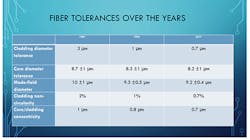
Older optical cables also have looser tolerances than today’s fibers. These tolerances mean that a percentage of fiber splices will have higher attenuation values. Re-splicing will not improve these as they are caused by internal fiber tolerances and not by the level of equipment or the skill of the splicer. This is important for designers to understand as they should not assign splice values of .1 dB or better if the older fiber tolerances do not allow low loss splices in many cases.
Legacy terminations must also be considered. In the 1990s, most fiber connectors used were the spherically polished Physical Contact (PC) with a return loss of 40 dB. Later, Super PC (SPC) polishes improved this to values of 45 dB. By the early 2000’s, this would be upgraded to the Ultra P.C. polish with 50-55 dB return loss value. In addition, dense wavelength division multiplexing (DWDM) and CATV analog systems using EDFA optical amplifiers required angled P.C. (APC) polishes to reduce reflections to 60-65 dB. (See Figure 1.)
Figure 1. Fiber quality has improved over the years allowing lower splice losses. (Courtesy FiberStory)
These polishes allowed systems to meet required bit error rate requirements. However, with today’s increasing data rates, older legacy (PC and SPC) polishes need to be replaced. If fiber was originally spliced with pigtails, new pigtails can be used to replace older ones. Or splice-on connectors (S.O.C.) can be used for individual terminations as needed. If unsure, an OTDR test can be performed to measure the reflectance values of the fiber connections to verify that they meet current requirements.
Before making any decisions, it’s important to evaluate the existing physical plant to confirm the quality of the legacy fiber and its terminations. Some of these details include the fiber type, count, and manufacturer. Installation dates are also helpful. For example, in the mid-2000 time frame, most fiber manufacturers shifted to low water peak (LWP) or zero water peak (ZWP) ITU-T G.652D single-mode fibers. They allowed expansion into the Extended band (E-Band) which operates in the 1360 nm to 1460 nm spectrum. This spectrum was designed for the future use of for coarse WDM (CWDM) systems. Legacy fibers have a fiber attenuation up to 2 dB/km in the E-band and normal 1310 and 1550 nm testing do not test in this spectrum. Testing the E-band requires either the use of a 1383 nm OTDR or a tunable OTDR.
When reviewing your physical plant, take a look at OTDR charts at 1550 nm or 1625 nm to make sure no macrobends nor microbends are present. This is important because longer wavelengths will be used in the future; these are more bend- and stress-sensitive. If high losses occur, a truck roll is required to redress the fibers and remove the macrobends (bend radius) or microbends (pinching effects) on the specific fibers identified.
Designing for the Future
A network designed for best routing may include legacy installations and also new segments. This brings us to updating and verifying our records for the legacy plant as well as the new segments. The data collected must include span attenuation, fiber counts, and optical return loss (ORL) values. Other challenges are to identify where existing single-mode fibers are placed in the outside plant and the number of dark fibers available.
Types of sites also dictate the fronthaul fiber sizing. This can differ for macro cells compared to small cells. Because most legacy installations do not have the number of fibers available to meet today’s demands, the better option is to build new infrastructure and install larger fiber count cables. Due to the amount of data being transmitted, designers should also consider ring topologies for feeder cables linking the core to the fronthaul drop cables. Should fiber exhaust be a problem, options to increase capacity include time-sensitive networking aggregators, coarse and dense wavelength division multiplexing (CWDM/DWDM).
Terminations are also a challenge as new SFP modules at the radio sites often use the high density MPO connectors which must be inspected and tested for attenuation and ferrule surface quality. At most equipment panels, traditional patch panels may be used with SC/UPC or LC/UPC terminations but may now include MPO stubs for mass splicing. The 12 fiber MPO can also provide quicker testing but requires new equipment as the MPO will also add a polarity test task into the testing. (Polarity testing assures that each fiber is routed correctly.) MPO connectors also have an angled endface so they have lower Fresnel reflectance levels when measuring reflectance and ORL.
One issue for installers is to recognize that connectors are specified for a number of mating cycles. In the case of the MPO, this can be as low as 200 cycles. Therefore connectors, patch cords, and loopbacks, used when testing spans, should be replaced periodically as they may exceed the .2dB repeatability standard established by the Telcordia GR-326 document.
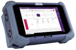
Figure 2. OTDR with 1310/1550/1625 nm wavelengths designed for 5G fiber testing. (Courtesy VIAVI)
5G Testing
The OTDR is used in backhaul, midhaul, and backhaul testing. Due to the shorter spans, an OTDR with a 30-dB dynamic rage is normally adequate. But the need for short pulse widths are required for testing the drop cables to the radio using MPO and loopback connectors. Besides the traditional 1310/1550 nm wavelengths, adding a 1625 or 1650 nm laser allows for locating macrobending and microbending stresses. (See Figure 2.)
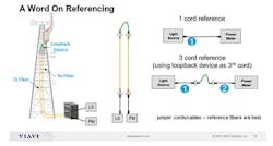
Figure 3. Loopback connectors provide a safe and efficient methods of testing on radio towers/sites. (Courtesy VIAVI)
The final connection is often one or more 12 fiber cable assemblies with factory-terminated hardened MPO/MTP connectors that allow for easy installation, including cleaning and testing. Due to the shorter distances and routing limitations the potential for bending stress losses is higher. Even with 3 SFP modules per tower, that requires 6 fibers. With 3 radios/tower this increases the fiber count to 24. The use of MPO connectors with rows of either 8 or 12 fibers allows for a safer termination by the use of factory terminated stubs (pigtails) at the top and base of towers. To minimize tasks and increase safety, testing is simplified by the use of loopback connectors which allow for the light source and power meter (optical loss test set) to be located in a physically safe location. However, visual inspection for surface quality is still required for the hardened MPO and loopback connectors. (See Figure 3.)
Like this Article?
Subscribe to ISE magazine and start receiving your FREE monthly copy today!
For backhaul and midhaul installations where CWDM or DWDM may be used to resolve fiber exhaust problems or limited dark fibers available, there is test equipment available such as WDM channel checkers and tunable OTDRs that can be used to sweep the spectrum required.
The key for all testing is to identity fibers out of compliance with specifications required to assure that the fibers can support new high-performance installations.
About the Author


