Latest from 5G/6G & Fixed Wireless Access/Mobile Evolution
The Symbiotic Relationship Between 5G and Fiber
The 1st Article in a Series of Fiber-Need-To-Knows —
In this article, and in several follow-up articles, I will focus on challenges that must be addressed when designing and building 5G networks operating over single-mode fibers.
The massive implementation of 5th generation (5G) radio technology with its ability to provide massive amounts of data offers a solution for bandwidth "on the go".
Single-mode fiber (ITU-T G.652D) has been proven that it is the best medium to use for transmitting huge amounts of bandwidth while also being able to address future bandwidth changes. As 5G can be transmitted over a range of frequencies, large numbers of cell sites are used to link service providers with a variety of different types for smaller cell sites for indoor and outdoor installations. These cover short distances involved or macro cells used in low density applications, and micro cells for areas with greater densities, and users using massive amounts of bandwidth.
InvisiLight® Solution for Deploying Fiber
April 2, 2022Go to Market Faster. Speed up Network Deployment
April 2, 2022Episode 10: Fiber Optic Closure Specs Explained…
April 1, 2022Food for Thought from Our 2022 ICT Visionaries
April 1, 20225G Transmission Systems
There are 2 basic types of radio transmission technologies used for 5G systems. Millimeter wave (mmWave) radios are designed for applications such as local neighborhoods where distances are shorter and the antennas are much smaller, and can be placed on light and utility poles. These have high capacity but limited coverage, and are deployed like small cells with power and space limitations. (See Figure 1.)
Figure 1. 5G Radio Antenna mounted on light pole. (Courtesy Maxcell)
The second type, known as Sub-6GHz, is preferred for larger coverage areas where there is a great deal of media demand.
Of course, there will also be situations where a blend of the 2 technologies will be required, such as side streets from public squares and business parks. These systems have lower capacity than mmWave, and utilize coverage similar to traditional cell towers and small cell deployments used by 4G LTE.
Depending on the application, distances involved, and density, designers must select a combination of these 2 or a blend of the 2 types of systems.
Fortunately, single-mode fibers with their high bandwidth, low attenuation, and low latency, provide the perfect medium for interconnecting various cell sites between the core of the network to the local cell sites, including back haul, middle haul, and front haul. The demands of providing higher bandwidths in the future is easily addressed with these fibers as their limitations of attenuation, optical dispersion, and reflectance, can be easily addressed at terminal equipment versus replacing the physical media in the future.
Design and Planning
Identifying the target is key. This includes defining the location, types of users and their applications, and the density for today’s requirements and for future needs.
Where does this bring us?
• Proper investigation and planning for the types of users, their current and future bandwidth requirements, and density of the service area.
• For example, in the case of high-powered Sub-6 GHz systems radio antenna, spacings can be as great as 2,000 feet as compared to local neighborhoods where lower power small cells with 200-foot spacings are common.
Due to the quantity of smart devices in use in a specific area, speeds from 10 to 100 times from a current transmission rate with a throughput of 100 Mb/s for 4G. But for 5G transmission, speeds of 2 Gb/s and higher will be required. What’s more is the need for symmetrical bandwidth due to COVID-19 network requirements. Previously, most residential customers were satisfied with asymmetric bandwidth.
The type of system will help identify the fiber quantity required. Accrued data rates of 300 Gb/s for 4G/5G sites may require higher fiber counts, especially when used in conjunction with sites where Multiple-Input/Multiple-Output (MIMO) antennas are deployed to increase link capacity. Even in the case of local small cells, data rates of 10 Gb/s bands per radio are not extreme.
Other challenges are to identify where existing single- mode fibers are placed in the outside plant, and the number of dark fibers available. When adding up the amount ofmacro and smaller micro cell radios, it is easy to come up with extremely large numbers of fibers required to link the transmission equipment.
Unfortunately, most legacy installations do not have the number of fibers available to meet this demand. The choice then is to build new infrastructure and install large-fiber-count cables or to implement DWDM technologies. Either way there are higher costs involved.
The types of sites also dictate the fronthaul fiber sizing, which can differ for Macro, Small Cell, In-Building, Venue, and Enterprise applications. These can be from 8 to 72 fibers depending on the applications and initial needs. Due to the amount of data being transmitted, designers should also consider ring topologies for feeder cables linking the core to the front haul drop cables. When planners add potential growth forecasts of 20%, extra fibers for spares are not uncommon.
Depending on the area served and strategy used, radios may require 8-12 fibers each to serve 16-20 homes if the service provided is using fixed-access antennas. The greater the amount of radios, the larger the fiber count. Should fiber exhaust be a problem, options to increase capacity include dense wavelength division multiplexing (DWDM) or coarse WDM (CWDM).
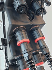
Figure 2. Hardened fiber optic connector. (Courtesy Senko Advanced Components)
For each small cell, the exact fiber counts will differ based on density, geography, and current and future requirements. Feeder cables are installed to connect the core network to the mid-haul and edge sites.
• Fiber counts of 864 and 432 fibers are often used with smaller 200-micron coated fibers to minimize cable diameters.
• As the installation gets closer to the end user, smaller count optical cables ranging from 12-48 fibers are used.
• The final connection is often 1 or more 12-fiber cable assemblies with factory terminated hardened MPO/MTP connectors that allow for easy installation, including cleaning and testing. (See Figure 2.)
Cable manufacturers have addressed space constraints and the need to decease cable diameter because:
• Hand holes are often used versus vaults in the outside plant.
• This, of course, requires smaller bend radius diameters.
• If larger conduit is used, manufacturers can also provide fiber counts up to 6,912.
• Because of the lower fiber counts and cable diameters, 2-inch PVC conduits with flex ducts are preferred.
5G and Future Requirements
Wireless technologies are limited in range and bandwidth without the use of optical fiber technologies. Fiber provides unlimited bandwidth over long distances between fixed locations.
For 5G to meet its potential:
• The distance between small cells should be between 200 and 1,000 feet.
• Also, to deliver at least 1 Gbps peak speed to each user, the minimum downlink speed to each small cell will need to be 20 Gbps.
• The uplink peak data rate will need to be 10 Gbps.
Like this Article?
Subscribe to ISE magazine and start receiving your FREE monthly copy today!
With peak speeds over 1 Gbps to the individual user and latency less than 1 millisecond, 5G would enable broader adoption of many technologies, notably including autonomous vehicles where low latency is required.
Depending on the location and application, bandwidth requirements can be much higher. Consider the broadcast industry and many pro-AV applications that are currently using 4 K resolution equipment. Today 8 K transmission is available but requires 4 times the bandwidth with 1.8 Gb/s data rates required for broadcast quality resolution.
One of the positive benefits of greater numbers of people working and learning from home is the massive implementation of FTTx and 5G networks. This evolution will continue to provide the bandwidth and reliability end users demand.


