Latest from C&E/NetDev Ops/GIS/Open-Source Networks
5 Stages to Nail the Moving Target of MDU Design and Installation —
Designing for a multi-dwelling unit (MDU) deployment is much like a game of darts. What comes into play are coordination, timing, and a laser-focus on hitting your targets. There’s more at stake in your MDU design, though, particularly as it relates to your bottom line and your subscribers’ ability to participate in our increasingly connected world. Now more than ever, a bull’s-eye in MDU deployments is an on-time, complete turn-up for residents and businesses to access reliable, high-speed broadband.
To achieve a particular outcome in darts takes an element of luck — another on-the-mark similarity with successful MDU designs and installations. Although much of an MDU project is planned and scheduled out weeks in advance, more often than not surprises and unforeseen challenges emerge. MDU installations encompass many twists and turns, both literally with cable pathways and spaces, and figuratively with the involvement of multiple stakeholders (including owners, contractors, service providers, and residents), each with their own expectations to manage and meet.
Let’s explore the design and installation stages within the context of the overall MDU project life cycle, taking aim at strategies for rapid, efficient deployments in new and existing buildings.
Stage 1: Predesign Verification
MDU sites targeted for either new or upgraded services begin with existing relationships or provisioning of legacy services. In the case of new (i.e., greenfield) deployments, communications between the service provider (sales team) and the developer or prospective building owner is paramount to ensure inclusion of the latest technologies and any related fiber-based services.
Developers often provide additional investments to incentivize the build-out with advanced telecommunications services that bear on marketing, access, and/or right-of-entry agreements. For existing buildings, considered overbuild (i.e., brownfield) deployments, access to customer-specific geographic information systems (GIS) databases and other publicly available location-enabled services can also help to identify potential candidates for upgraded services. To the extent possible, streamlining and facilitating the property management approval process should be the primary objective, and this often depends on communicating a design proposal as early as possible in the overall project life cycle.
The design and installation process often begins with a site validation, especially for brownfields, and/or a pre-engineering meeting in the case of greenfields. It is during this stage that items such as the minimum wiring standards, conduit proofing, cable pathway evaluation, as well as provisions and requirements for power (UPS) and optical network terminal (ONT) mounting, will be established. Common issues that arise include lack of sufficient backboard space for the ONT in fiber-to-the-closet/IDF installations, upgrades to the environmental controls in the room or closet for the ONT electronics, and establishment of grounding locations.
Local codes (per NEC®) will often determine the final bonding and grounding specifications, possibly requiring an electrician to rewire or identify a sufficient grounding network. Riser pathways are also inspected to assess any proofing requirements and feasibility for additional pulls. Horizontal drop routes are evaluated to determine the number of 90-degree bends they’ll encounter or if firestops need to be replaced and redone.
Fiber-to-the-unit (FTTU) service is desired in most metropolitan areas, as it offers the highest data speeds with prevailing electronics and protocols, and it represents the majority of new and overbuild situations today. However, buildings with embedded CAT 5e cabling or greater make good candidates for at least fiber-to-the-closet or intermediate distribution frame (IDF) deployments. Environments with CAT 3 may require interim solutions such as G.fast, which typically offers maximum download speeds from 300 to 500 Mbps in actual deployments. However, G.fast for some providers is ruled out because of obsolescence and interoperability concerns.
Bulk Wi-Fi is another option in some overbuild scenarios, in which the MDU property owner purchases multitenant Wi-Fi access and resells it. Frequently, penetration and propagation of the wireless signals can become a challenge in older buildings (think thicker walls and doors) and even in some of the newer, more energy-efficient (LEED) buildings, in which windows include metallic coatings and/or inert gases that corrupt cellular signals. Distributed antenna systems (DAS) can offer a potential solution when cell coverage in particular is an issue. Updates to existing cable and MDF electronics might also be warranted to accommodate these solutions. Wi-Fi is often reserved for common areas in the building or related gratis services (lobbies, retail areas, etc.).
Stage 2: Project Entry and Submittal
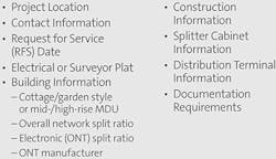
Once a particular project has been deemed economical by all project stakeholders, the initial project requirements are developed and documented. Determining a target ROI drives the analysis of product, installation, and engineering factors for the project. Many factors are common to single-family unit designs and include the number of living units passed, anticipated take rates, distance to and from the associated central office or telecommunications hub, and so on. One of the most important submittals to initiate the design process is a document that itemizes the specific installation requirements, and in which project plan details and timelines are defined. (See Figure 1.)
Figure 1. Project Plan Requirements
The project’s scope can include both the feeder (F1) and distribution (F2) facilities leading up to and within the MDU. Drop cables (F3) may or may not be within scope. If fibers need to be identified and accessed in the existing outside plant (OSP) network for the F1 cable serving the MDU, this will also be described in detail in this section, in addition to any optical and/or electronic (OLT/ONT) split ratios planned for the network. Pertinent equipment details for the central office and transport fibers might also be called out in addition to an anticipated optical budget for all relevant channels of operation. Also important to the document are the appropriate points of contact for resolving any missing or incomplete project requirements.
Stage 3: Project Scheduling
The estimated move-in or "request for service" date for occupants is one of the primary drivers for the project scheduling. Following in importance are any associated open or joint trench dates in which the F1 cable installation feeding the MDU will coincide with any other utilities. This in turn will drive materials management and procurement. Missed deadlines not only introduce delays, but they can also cause entire redesigns based on new product sets for the installation method; for example, a nonduct solution turns into a duct solution because of a missed trench date, or a wall-mounted panel solution becomes a rack-mounted one or vice versa because of used-up mounting spaces.
F1 cable installation scheduling must also coincide with any necessary permitting required by the city or county for accessing maintenance handholes, right-of-way trenching, and handhole placement. This requirement also applies to F2 cables that are run outside in garden-style or campus layouts for multiple MDUs or townhomes. Aerial considerations can also have an impact along the lines of permitting for power poles owned by others, tree trimming, traffic control, and even trolley-crossing deactivation in some areas of the country! Not even getting into how weather can influence the best-laid plans, it’s understandable that missed requirements can delay or force a revisit to prior steps of the overall process.
Once inside the building, and in particular with new buildings, the rate of drop (F3) installation is often correlated with the rate at which walls (sheetrock) go up. This process can be lengthy. Cable can be tested and terminated at a much faster rate than it can be routed — work that is typically performed by the low-voltage electrician. For brownfield installations, you have entirely different challenges, including congested pathways (4-in steel conduit, for example) for the riser distribution, challenging horizontal drop routes, and solutions that must integrate with existing building aesthetics.
Grounding requirements for patch panels and electronics can also further impact installations, depending on local codes and necessary updates.
Stage 4: Site Walkout
The service provider is responsible for the initial documentation, but a site walkout will be required by the relevant contractor, project manager, or field technician to fill in missing information and to carefully document and photograph all relevant cable paths and spaces. The design process often begins during walkout, in which the entire cable route is inspected from the intended point of feed (POF) to the building living units. For MDUs, it is almost always necessary that the site walkout occur either before or in parallel with the design process to minimize needless revisions.
Stage 5: Design Process
Having a consistent and sequential process is essential to proper project execution; but often, various aspects of the project occur in parallel and can benefit from a reliable and mobile software platform. The initial design might begin with a rudimentary sketch on which cable and conduit pathways, locations, and provisions for patch panel mounting, potential obstacles, and other installation requirements, are identified on a drawing or base map. Typically, a floor plan or overall base map image serves as the context for notes, line diagrams, identification of access points, and correspondences that occur between the designer and the field technician/inspector.
From this point, it is critical to track the design progress and update revisions as they occur to ensure consistent communications and understanding between involved parties. Moreover, being able to automate and deliver a report on the design allows property managers and/or building owners to understand its impact on the building’s facilities and aesthetics, and to feel comfortable in granting final approval earlier in the overall process.
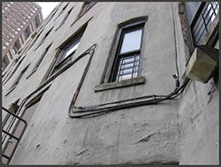
Figure 2. MDU Façade Installation
During these formative design stages, the process can be somewhat iterative, in which the designer and field personnel cross-verify submitted project requirements vs. what has been observed on-site. For example, inconsistencies in scaled distances, or differing facility locations from submitted drawings might be uncovered. Living unit addresses and other basic services will also be identified, such as alarm, elevator, office, security, and retail facilities. This step may reveal that riser facilities are nonexistent or are too congested to use, requiring a "façade" installation on the side of the building — and a completely different on-site analysis. (See Figure 2.)
Newly available MDU software design and documentation tools can help simplify, standardize, and accelerate, the survey and design process. With proper implementation of a mobile MDU design and documentation software platform, real-time exchange of communications between the field and the office in the form of marked-up drawings, field notes, and other submittal items, will successfully and efficiently drive other required tasks and actions.
The schedules that personnel have to follow when managing multiple projects often prohibits waiting on them to return to the office to distribute field notes without adding time to the project clock. Moreover, lack of building access (a key to the closet, fire-escape stairs, etc.) and poor cell phone reception can also impede communications and cause additional delays.
MDU design falls upon principles and methodologies that are often used in traditional FTTH deployments, specifically the location and split ratio of optical network splitters. Take rates are generally above 80% in MDUs, especially in major metropolitan areas. The main concern with proper establishment of split ratios is in the provisioning of bandwidth. The service provider often determines this requirement based on the particular suite of electronics being deployed, but split ratios of 1×8, 1×16, 1×32, and higher, are all commonly used. GPON WAN interfaces are still the predominant protocol suite deployed today for Gigabit speeds to the living unit. This expectation is reaching utility-level demand in major metropolitan markets, but XG-PON, XGS-PON, EPON, G.hn, NG-PON2, 10G EPON, and even DOCSIS 3.1-based technologies, might also be encountered or considered. Also, many of these platforms offer instant turn-up using an integrated ONT/modem and regular monitoring and diagnostics by the service provider once tenants move in and are ready to take service — an important factor in service quality in an environment where customer turnover/churn can be several times higher than in single-family homes.
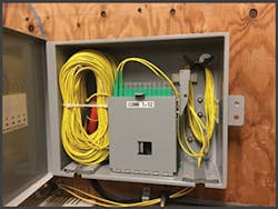
Figure 3. IDF Riser Terminal
Cabinets and terminals that support splitter upgrades through plug-and-play technology are typically specified to support future needs of consumers. Product sets that allow rapid deployment (e.g., MTP® connectors) and testing enable network operators to deploy fiber fast – especially important in brownfield scenarios where minimizing inconvenience to existing occupants is imperative. (See Figure 3.)
The contractor that can deploy a solution during the limited window in which tenants are at work "hits the mark" and often wins the job.
Additionally, these products have to meet proper UL testing requirements to satisfy local codes and inspections. In the horizontal, products that work with existing pathways (such as latch-duct), or blend seamlessly with exiting corridors and hallways are ideal. F3 drop cables can be ordered to length and preterminated on one or both ends or measured from bulk reels to accommodate route-specific lengths and terminated with mechanical connectors. Often, the horizontal pathway includes both lateral and vertical routing to the living units. Lastly, for FTTU installations, a "smart" panel often must be placed that allows mounting of the ONT in the unit.
Bull’s-Eye!
For those considering taking on any aspect of MDU design and installation, this overview provides a glimpse into the logistics and challenges that must be considered to implement a project plan aimed at success. From the initial project charter all the way through the final closing of the project, it is vitally important to clearly define requirements and implement an operations management strategy that establishes and reinforces specific process tasks and guidelines. Along every step of the way, the ultimate goal is to ensure proper functionality, reliability, and on-time service delivery. The general rules for success in this environment are first, do not assume anything, and second, be flexible and anticipate changes needed to hit each milestone or deadline throughout the project life cycle.


