Latest from C&E/NetDev Ops/GIS/Open-Source Networks
You Best Know the Latest Advances in Field Surveying.
With the advent of Internet of Things (IoT), 5G, and Fiber-to-the-X (FTTx), the demand for optical networks is growing exponentially. The related growth of the optical networks will not allow for traditional methods of design as the cost is too high and these older methods can delay timely deployment. What is needed today in field surveying is not the standard Rural Utility Service (RUS) Staking sheet with stationing details aligning with Department of Transportation (DoT).
Instead, today’s surveying requires: survey-grade Global Positioning System (GPS) points with high-quality images, a reflection of what the underground looks like, and measurable images that allow back-office validation or capturing of all construction obstructions.
In this article, we explore 4 tools that offer those things:
1. Light Detection and Ranging (LiDAR)
2. Subsurface Utility Engineering (SUE)
3. Aerial Survey
4. Global Positioning System (GPS)
Light Detection and Ranging (LiDAR)
LiDAR is an optical remote-sensing technique that uses laser light to densely sample the surface of the earth, producing highly accurate X, Y, and Z measurements. LiDAR produces mass point cloud datasets that can be managed, visualized, and analyzed.
Traditionally LiDAR is viewed as an airborne process. However, to maximize the capturing accuracy, the use of terrestrial LiDAR is needed.
LiDAR allows for capturing 3D images of the terrain that is measurable and a video-style image capture allows for the back-office engineer to see the terrestrial image, thus improving their knowledge of the true field conditions.
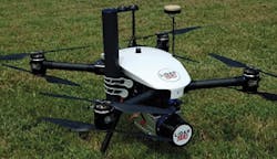
One of the limitations of LiDAR is the visible nature of the data points; if the laser and camera cannot see it then the back office cannot see it. The traditional method of aerial or vehicle-mounted LiDAR creates these blind spots, but using small drone-mounted, ATV/UTV, backpack mount, etc., LiDAR systems, these blind spots can be eliminated. (See Figures 1, 2, and 7.)
Figure 1. Drone LIDAR (courtesy of Lidar USA).
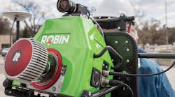
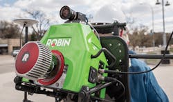
Figure 2. Backpack LiDAR System (courtesy of 3D Laser Mapping).
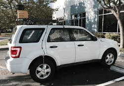
Figure 7. Vehicle-mounted LiDAR system.
The key would be to use a hybrid of these solutions allowing for speed through vehicle-mounted systems, and addressing the blind spots via the small mounted systems. By using these LiDAR systems, the detailed technical skill set of the field surveyor can be minimized, reducing cost for field survey.
As you can imagine, LiDAR creates massive amounts of data that requires post-processing that allows the back-office engineer to mark all key terrestrial (visible) obstructions that could impact the build phase. Thankfully, tools are available (or can be created) that automate object identification and marking within the data points which reduces the repetitive task for the back-office engineers.
With the creation of survey-grade level GPS, along with the automated marking, the creation of high-quality base map layers can be made with all key obstructions properly marked. With this quality detail, the use of a rules-based design tool can often create a 95% design. This requires the back-office engineer to effectively review and slightly adjust.
LiDAR can capture an average of 68 miles daily. However, it is best to capture smaller segments of approximately 24 miles, then resync and begin capturing the next segment. In this manner, the GPS and images stay properly aligned. Post-processing varies based on the number of points to mark and the processing server power.
Subsurface Utility Engineering (SUE)
One of the greatest challenges for subsurface design is the lack of knowledge of what is truly underground. Old, out-of-date as-built prints, engineering locates, etc., are the major reasons for the occurrence of utility strikes (Horizontal Directional Drilling (HDD), trenching, plowing, etc.). Unfortunately, the problem is compounded with the use of high-density polyethylene (HDPE) and reduction of metallic elements within the materials using electro-magnetic (EM) (Radio Frequency (RF) locators.
Should locates be accurate they are normally accomplished only a couple of days before construction, so are of no value during the engineering phase.
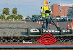
Many think Ground Penetrating Radar (GPR) is expensive and has limited value, except in the locating phase. However, this perception is inaccurate. Based on soil mechanics and post-processing, the types of underground infrastructure can be identified and automation can then mark these elements. (See Figure 3.) Once identified and marked, this information can then be placed as a layer on the base map. With this subsurface base layer, a rules-based design tool can then design based on known subsurface obstructions.
Figure 3. Ground penetrating radar.
The knowledge of the subsurface allows properly identifying pathways of other utilities — which is a key factor in permit packages. With this and the other base maps, tools are available that allow for automated creation of the permit packages.
With the use of GPR, the ability to know the rock conditions in the proposed pathway is also possible. This helps reduce the unknown cost factors before the build begins.
With a vehicle-mounted GPR system, the average daily capture using this method can be approximately 50 miles per day. Using a walk-behind GPR approximately 9 miles per day can be accomplished per unit.
Aerial Survey
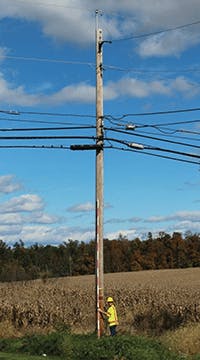
"Time to go stick the poles" entails using measuring sticks, wheels, GPS, range finders, tape measures, cameras, and paper or computer. (See Figures 4 and 5.)
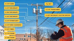
Figure 4. Post-processed with PLA form (courtesy ikeGPS).
Figure 5. Measuring stick for offset measurements (courtesy Katapult Engineering).
Once the data is collected, the make-ready engineer (MRE) must enter the data into the pole loading analysis (PLA) software. In addition, someone will have to post the location of the pole(s) into the design tool if this is not automated. The challenge with this method is that it is very subjective based on the skill set of the field surveyor. This means the consistency of the data can vary dramatically. As you can imagine, the average number of poles able to be surveyed is limited. In fact, this method yields about 10-12 poles per day per surveyor, due to the amount of equipment and the nature of "sticking" a pole.
Automation of this process varies, from marker sticks, GPS, and high-quality cameras that provide the ability to measure the attachments when tied to the marker pole height, to a completely automated tool that has built-in GPS, distance ranging, and camera. One of the key benefits of the semi-automated systems is that the PLA forms can be loaded onto the tools thus allowing for direct digital input into the software reducing the double entry. When using these tools, the normal capture rate is approximately 30 poles with PLA forms and 75 poles without PLA forms.
This significantly increases the daily capture rate in the field. However, key to this is the quality of the data captured. If the base of the pole is not visible due to over-growth then some form of visible height marker is required, allowing an offset measurement. So, the field surveyor must have a fundamental skill set to properly input the data into the PLA form and a focus on detail to ensure quality field capture.
Using these semi-automated tools, the benefit is level of accuracy and speed in the back office. Using the PLA forms, the MRE can mark attachment heights, verify the data (pictorially), and then load it into the PLA software in less than 10 minutes or so per pole. When done manually, the average MRE can handle approximately 20-25 poles per day compared to 40+ poles with automation.
With the challenging nature of pole attachments, the quality of the PLA and make-ready package that is presented to the utility pole owner relates to timely approvals. The higher the level of quality and accuracy, the greater chance for improved timely approvals.
Global Positioning System (GPS)
Global Positioning System (GPS) is key in today’s design. And the data collector is critical in this process.
There are 3 categories of GPS Receiver with accuracy level of:
1. Recreational Grade: +/- 100 feet
2. Map Grade: +/- 10-15 feet
3. Survey Grade: within centimeter or even millimeter
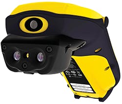
It is also important to use survey-grade GPS receivers inclusive of your LiDAR, GPR, and Aerial survey tools, to obtain the level of accuracy needed for automated design tools. (See Figure 6.) These collectors can be used in lieu of or in conjunction with the LiDAR by walking the route and manually marking the visible obstructions. This can then be imported into the design tool to create base map layers.
Figure 6. Survey grade GPS receiver with built-in range finder.
The Bottom Line
Speed and accuracy is critical in today’s network deployment phase. The use of automation in the field survey process addresses many issues related to the skill set of field surveyors. These tools also provide a quicker turn-around and reduce manual design efforts and data input. All this translates to cost savings and quicker speed to market.
Save


