Latest from Columnist

It’s Time to Surrender Your Breakdown Set: Part 2 —
This article continues our original exploration into problems associated with troubleshooting paper/pulp insulated cables. (See "The Search for a Better Mousetrap: It’s Time to Surrender Your Breakdown Set: Part 1" in our October 2019 issue: https://isemag.com/2019/10/the-search-for-a-better-mousetrap/)
As I previously shared, it’s important to remember that this type of copper network with paper/pulp insulated cable is sealed. Therefore, fault isolation is difficult because we are unable to "divide and conquer" efficiently. Tone-based fault locating has been the traditional method for decades.
In the past, fault locating occurred by using a breakdown set. The concept behind this is simple: the tone is connected to a bad cable pair and it stops at the fault. If the fault is 0-Ohm (metal to metal) and no other path to ground is present, you find where the tone stops and open the cable there.
InvisiLight® Solution for Deploying Fiber
April 2, 2022Go to Market Faster. Speed up Network Deployment
April 2, 2022Episode 10: Fiber Optic Closure Specs Explained…
April 1, 2022Food for Thought from Our 2022 ICT Visionaries
April 1, 2022In this article, we tried using a different strategy. Let me set the scene.
• Date: June 13th, 2019
• Location: Eastern Missouri
• Weather: Rain until 9:00 AM, Clear until 3:30 and then hailstorm
• Condition: Wet pulp cable
As we experimented with this new tool, our goals were simple:
1. Find the location of a wet pulp cable using a low (non-zero) ohm shorted cable pair
2. Find the location of a wet pulp cable using a low (non-zero) ohm battery crossed cable pair
Cable Fault Locating
With wet pulp, most pairs have shorts, grounds and battery faults. Grounds make tone fault locating so much more difficult. This is because grounds will cause the fault locating tone to carry by the fault location. The tone changes beyond a grounded fault and with experience, you can detect the changes. Still, only troubleshoot a ground in sealed cable if you have no other choice.
Ca Pr 305 – 2k ohm short
• Pretty solid ground
• TDR showing something at 2,722 feet
Ca pr 355 – 220 ohm short
• Ground both sides
• TDR showing something at 2,788 feet
Ca pr 374 – 20 volts
• TDR showing something at 2,800 feet
Ca pr 391 – 336 ohms
• No battery
• Ground both sides
When we began, the TDR readings all showed an event around 2,700 feet from the office. (See Figure 1.) The first access point beyond the CO was around 6,000 feet from the office. This is why tone-based fault locating is so desirable.
Figure 1. Fault Location.
Using a TDR or RFL, you can get close to the fault and then isolate it. The problem with isolating in pulp cable is that every test requires an open sheath or closure that must be closed and sealed after the test. Using tone that stops on the fault allows you to open the sheath just at the spot of the root cause.
Every cable pair having low resistance grounds made this a very difficult investigative scenario. There were low expectations that the tone would stop at the fault. A tone change was much more likely.
Testing Technique
While we could have used the traditional breakdown set to move forward, our goal was to see if an alternative would be effective. With this new tool, tone level and frequency impact the accuracy of this technology, so we started by using the auto mode setting.
Pair 355 was chosen, and the transmitter chose 987 Hz as the proper frequency. The process consisted of connecting the cable pair and pressing 2 buttons.
The receiver setup is marginally more difficult than the transmitter. (See Figure 2.)
Figure 2. Receiver screen.
There are 3 settings that significantly impact accuracy:
• Frequency = must match transmitter setting
• Gain = level of tone received
• Volume = level of tone heard
Figure 3. Setting the benchmark.
With the transmitter sending tone, we went to the first access point from the CO to set the benchmark on the receiver. (Since everyone’s hearing is a little different, personal preference greatly impacts these settings.)
The key is to set the receiver where the tone can be detected, and the user can physically hear the tone. (See Figure 3.) Once the settings are in place, you should not change them without starting over again with a new benchmark.
Since this wet cable runs through alleys, we were fortunate that traffic was only an issue when crossing streets. Especially when using headphones, be sure to watch for cars and other hazards.
Given that the tone travelled well beyond 2,700 feet, it was assumed that the ground fault was causing the tone to run by. Pair 391 was tried at 330 Hz and it also blew by 2,700 feet. Then we found a tone change about 600 feet beyond the 2,700 mark.
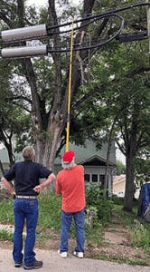
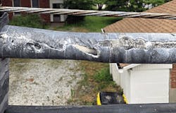
We discovered a squirrel bite that could be seen from the ground on the CO side of what we named the "The World’s Longest Sleeve". (See Figures 4 and 5.)
Figure 4. Squirrel bite damage to lead sleeve.
Figure 5. The World’s Longest Sleeve.
Beyond the squirrel bite, the tone changed:
1. The tone became distorted
2. The tone was suddenly present on the strand
The tone had stopped completely before the field side of the long sleeve. Taking the ground faults into consideration, this was outstanding performance.
What Happened at 2,700 Feet?
Even with an experienced team, we mistook a "smart" load coil for a fault. The TDR measured an event at 2,700 on every pair. Since we assumed it was the fault, we wasted considerable time disproving our incorrect assumption.
Again, this is why tone-based fault locating is important in sealed cable. Even the experts can be fooled with the latest TDR and RFL technology.
From a repeater case field side of the squirrel bite, we gained access to another cable pair wet at the same place. The transmitter was moved from the CO to the repeater site. It chose 330 HZ.
We walked 1,500 feet, taking tone samples every few hundred feet. The tone stopped exactly on the squirrel bite.
Like this Article?
Subscribe to ISE magazine and start receiving your FREE monthly copy today!
Interrupted
As we were testing a third cable pair, the skies opened up and lighting was all around us. Nobody was going to hold that long stick in the air, so we shut down.
When we determined that all the pairs had low resistance ground faults, expectations were low. The performance of the technology under these conditions was a pleasant surprise.
The joint team accomplished their goals. There is a viable replacement for the breakdown set available.
Is this technology the end-all, be-all savior for every cable fault? No, but the breakdown set was not either. No single test set is.
This article was intended to run in the November print issue of ISE Magazine. We apologize to readers who were looking for it in the issue of ISE Magazine. It will now be featured in the January 2020 print issue of ISE Magazine as well.

Vernon May
Vernon May is the Chief Technologist and Founder of Vernon May Solutions. He is an expert in OSP and ISP Operations, and focuses on new technology introduction, from marketing and sales to design enhancement to training to product approval. Along with writing a column for ISE magazine, he also hosts seminars available throughout the country.
For more information, call Vernon at 1.319.238.0285, email: [email protected], visit https://www.vmaysolutions.com/, and follow him on Twitter @Vernonmay13.
