Splicing Subtleties Matter —
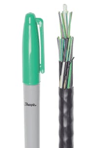
For decades, nearly all telecom optical fiber has had a nominal coating diameter of 250-microns. With growing demand for smaller cables, that has started to change. Many cable designs have reached practical limits for diameter reduction with standard fiber. But, a smaller fiber allows additional reductions. (See Figure 1.) Fibers with 200-micron coatings are now being used in Flexible Ribbon and Microduct cable. If you haven’t seen a 200-micron fiber yet, get ready, because you will soon.
Figure 1. 200-micron fibers enable ultra-compact designs like the 528 count cable above.
This article helps users understand what’s different about 200-micron fiber — and what’s not. It focuses specifically on splicing practices, which differ significantly for ribbon. The takeaway is a simple action plan for how to prepare.
Please note that during the rest of this article, we talk exclusively about fibers for commercial telecom applications. There are a wide variety of specialty fibers with different core, cladding, and coating ODs, that we don’t have space to cover here.
Good News
One of the most important things about 200-micron fiber is what hasn’t changed. The glass dimensions for 200- and 250-micron fibers are the same. The nominal cladding diameter is still 125-microns. This is a big deal, because a change to the cladding diameter could be very disruptive.
There is no direct effect on the fiber core, either. Once you strip away the coating, a 200- and 250-micron fiber of the same type (e.g., G.657.A1) is completely identical.
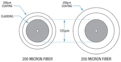
Because the glass dimensions aren’t changing, all the dimensional changes are being made to the coatings. As you can see in Figure 2, the primary and secondary coatings are thinner on a 200-micron fiber.
Figure 2. Dimensional comparison of 250- and 200-micron optical fibers.
Fiber coatings help to isolate the glass from stresses that can increase optical losses. For this reason, 200-micron fiber is normally produced only with "bend-insensitive" core profiles. The improved glass performance offsets the reduced coating performance.
The most common glass profiles for 200-micron fiber are G.657.A1 and G.657.A2. The standards require both fibers to also meet the requirements of G.652 (Standard Single Mode Fiber). This assures compatibility with existing networks. In keeping with current trends, these fibers are usually Low Water Peak designs (G.652.D or C).
InvisiLight® Solution for Deploying Fiber
April 2, 2022Go to Market Faster. Speed up Network Deployment
April 2, 2022Episode 10: Fiber Optic Closure Specs Explained…
April 1, 2022Food for Thought from Our 2022 ICT Visionaries
April 1, 2022G.657.A2 fiber has better bend performance, but typically has a smaller Mode Field Diameter (MFD) than Standard Single Mode Fiber (SSMF). MFD distributions for G.657.A1 fibers are similar or identical to SSMF. Some key attributes are summarized in Figure 3.
Figure 3. Select attributes for popular Single-Mode Fibers.
3 Things to Know
In terms of how 200-micron fiber changes splicing activities there are 3 things to remember.
1. Connectors
Because the glass is unchanged, there is no direct impact on connectors. Ferrule sizes should remain the same. Diameter reduction is the purpose of 200-micron fiber. So, if you want a 900-micron tight buffer, you should specify 250-micron fiber.
2. OTDR Measurement
OTDR measurements are unaffected by coating changes, but there are some things to look out for if you are using a new type of glass. False "gainers" and "losers" are more noticeable in uni-directional OTDR traces when G.657.A2 fiber is mixed with G.657.A1 or SSMF. These artifacts are caused by differences in MFD and can occur in any splice. (See Figure 3.) According to ITU, IEC, and TIA standards, Bi-Directional averaging is required for determining the true loss at any splice point.
3. Fusion Splicing
The impact of 200-micron fiber depends on whether you’re doing single-fiber or mass fusion splicing. This is because the fiber coating dimensions usually matter only during mass fusion splicing.
Single-fiber splicing is basically unchanged. Most single-fiber splicing tools are keyed to core profile or cladding OD, which remains unchanged at 125-microns. These tools will process individual 200-micron fibers just like 250-micron fibers. It’s usually not a problem to splice an individual 200-micron fiber to a 250-micron fiber. So, your existing single-fiber splicing equipment and processes are probably fine.
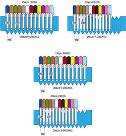
Mass Fusion (or ribbon) splicing is a bit more complex. Ribbon splicers use V-grooves to align the fibers for splicing. If the spacing of the fibers in the ribbon differs too much, it will be difficult to position the fibers properly for splicing. (See Figure 4.)
Figure 4. Mass Fusion Splicers designed for 250-micron fibers may not be compatible with ribbons made from 200-micron fibers.
Most Ribbon splicers were designed for 250-micron fibers. (See top of Figure 4.) Ribbons made with 200-micron fibers won’t naturally align with the V-grooves in these splicers. (See bottom of Figure 4.) So, splicing ribbons of 200-micron fibers requires a change in splicer or accessories.
Some splicer vendors have released new machines specifically for 200-micron fiber ribbons. The chucks and V-grooves are optimized for ribbons that are both narrower and thinner. However, these splicers are not set up to splice ribbons made with 250-micron fibers. This limits their use to splices with 200-micron fibers on both sides.
Some splicer vendors are also working on tools that would allow 200-micron ribbons to be adapted to 250-micron ribbon splicers. This can be done in different ways but has the effect of spreading the fibers precisely to match the wider V-grooves. This allows the use of existing equipment and allows "mixed" splices (200-micron on one side, and 250-micron on the other). Since the fibers are being spread out, the individual fibers in the 200-fiber ribbon must be separable.
Like this Article?
Subscribe to ISE magazine and start receiving your FREE monthly copy today!
Summary
The demand for smaller cables has created a market for 200-micron fiber. This fiber can provide significant diameter reduction in cables, while maintaining the same glass diameter. Still, it’s important to pay attention to a few subtle differences that will affect your success with fiber handling and splicing in the field.
About the Author


