Latest from Home
Eight-Step Refresher on Grounding
by: John Howard
(This article originally ran in the August 2011 OSP Magazine)
Although most people recognize that grounding is required for personnel protection, the grounding system also serves as the basis for the electrical protection of your site or facility. It determines the effectiveness of the lightning protection and surge suppression systems. Without good grounding, these systems do not function. Grounding also serves as the path for system noise to be dissipated from equipment.
The purpose of this article is to provide 8 simple steps for properly testing an installed grounding system utilizing the Fall of Potential method.
The Fall What?
The Fall of Potential method is the most recognized method for measuring the resistance to earth of a grounding system, or the ground system performance. It is based on an IEEE standard, and when properly performed, is a very accurate test.
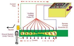
In the fall of potential test, 3 points of ground contact are considered:
- The grounding system under test (X).
- A current return probe (Z) placed some distance from the ground system under test.
- A voltage probe (Y) that is inserted at various distances between the system under test and the current probe.
Ideally the X-Z distance should be 10 times the ground rod length or grid width (i.e., 10 ft. rod, 100 ft. spacing). (Note: The author’s experience has shown that the [Z] probe may be placed at a minimum 5 times the length of the ground rod under test [i.e., 10 ft. rod, 50 ft. spacing]. If a grid is being tested, the minimum distance is 5 times the widest point of the grid.) (See Figure 1.)
Figure 1. Principle of Operation.
However, always go 10 times if the space is available. Evaluating the test results is the only way of validating the results and determining if the distance was adequate.
With this method of test, the meter is a current source and injects a current into the ground system under test (X). The current flows through the earth to the remote current return probe (Z) and returns to the meter. As the current flows through the resistive material (earth) a voltage drop is created. This voltage drop is proportional to the amount of current flow and the resistance of the ground system to earth.
The voltage probe (Y) is used to measure this voltage drop. The meter then knows both the amount of current flow and the resulting voltage drop. It simply uses Ohm’s law to calculate and display the resistance.
If the meter is causing 50 ma to flow through the ground system and it measures a voltage drop of 1.25 volts, E/I=R, 1.25/.05 = 25 ohms resistance to earth. Of course the meter does this internally; the operator sees only the final result in the readout.
The resistance is measured at several locations by moving the voltage probe (Y) at regular intervals, each of them equal to 10% of the X-Z distance.
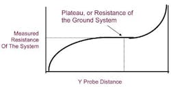
The resistance measurements are then plotted along with the distance between the ground system and the Y probe. From this graph the actual ground system resistance can be determined along with the validity of the test. (See Figure 2 for a valid test graph.)
Figure 2. Valid Test Graph.
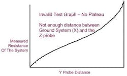
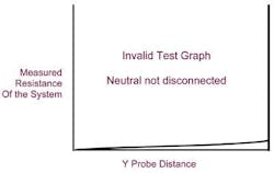
The grounding system must be electrically isolated from the utility neutral conductor for the Fall of Potential test to be valid. If not isolated, the readings will reflect all the grounding systems in the area, all connected in parallel. The reading will always be very, very low and have no bearing on the actual ground system resistance. The result is not just an inaccurate test, but is a totally invalid one. The results of an invalid test are shown in Figures 3A and 3B.
Figure 3A. Invalid Test Graph 1.
Figure 3B. Invalid Test Graph 2.
Electrically isolating the grounding system from the neutral conductor is virtually impossible at an operating facility. This makes the Fall of Potential test more useful prior to a facility becoming operational or when it is shut down for maintenance.
Don’t Give Up
If unable to isolate the ground, an actual Fall of Potential test is not possible. However, a test may be performed with the Clamp-On test meter, or on a part of the ground system may be possible. If installed less than 5 years, the ground system may be reverse engineered. Regardless, the system can be evaluated by qualified personnel, and a valid determination of whether any remedial actions are required. Check with a professional.
A last word of caution prior to the detailed procedure: Because the test injects current which flows through the ground, a metallic pipe, etc., may adversely impact the test results. To protect against this, when possible at least 2 perpendicular tests should be performed. Outlying data should be dropped and the remaining results averaged.
The grounding system must be electrically isolated during this test. This should be performed only by qualified personnel and after permission is granted by all responsible personnel.
Eight Steps Won’t Fail You
Before beginning, you must gather 5 pieces of critical equipment to perform this test accurately:
- A 4-Pole or a 3-Pole Digital Ground Resistance Tester
- At least 3 probes
- Insulated wire leads
- Tape measure
- Hammer (to secure probes into earth)
Now that you have everything you need, a simple 8-step program can help you ensure everything and everyone is protected on your watch:
Step 1. Isolate the grounding grid under test from all other supplemental grounds (i.e., water pipes, building steel, etc.). Also disconnect any neutral connections and all telco.
Step 2. If a 4-pole ground resistance meter is used, some meters require a connection between the C1 and P1 terminals. If a 3-pole ground resistance meter is used, no connection between the terminals is required.
Step 3. Connect the C1 connection to the ground rod or system to be tested.
Step 4. Install the current probe (Z) at a distance equal to 5-10 times the length of the ground rod or 5-10 times the diagonal distance of the ground grid under test. If a ring or grid is being tested, the distance must be measured from the outer edge of the ring. The probe must have good contact with the earth. Connect this probe to the C2 connection on the meter.
Step 5. Install the voltage probe (Y) at approximately 3% of the distance from the ground system and the (Z) probe. The (Y) probe must be in line with the ground and the (Z) probe. Connect the probe to the P2 connection on the meter.
Step 6. Push button to activate the meter. When a measurement is shown, allow the reading to stabilize and record the reading in a chart.
Step 7. Move the (Y) probe to 10% of the distance between ground system and (Z). Test as in Step 6 and record the results in a chart. Repeat this step (moving the probe at 10% intervals) until the 90% distance is reached.
Step 8. Once all the readings have been recorded, plot a graph with the measured resistances as the y-axis. A plateau will be evident if the test is performed properly. The resistance at this plateau is the resistance of the system under test. If there is no leveling of the plot, then the test is to be considered invalid since the (Z) probe is not far enough from the (X) probe (ground system under test). If the plateau is very low and flat, then the test is probably invalid and most likely still has an intentional or unintentional neutral connection.
If difficulty is encountered in obtaining readings, it is most likely caused by a high probe-to-earth resistance. Pouring water or Gatorade on the probes sometimes helps. This will not have any significant effect on the reading.
If available installing longer probes that provide a more surface contact may also help. Some meters have less difficulty overcoming the probe-to-earth resistance than others.
Perform additional testing in at least 1 perpendicular direction. The readings should be averaged.
It’s Worth the Added Effort
There are several benefits to a properly tested grounding system. Because of the critical role in the protection and performance of equipment, manufactures most often require a certain performance level prior to honoring their warranties. Damage and outages due to lightning and surges can be virtually eliminated by properly installing grounding, lightning, and surge protection devices. Far less maintenance and downtime will be experienced with protected equipment. The performance of your ground system should not be left to guesswork — make sure it meets your specifications.
John Howard, VP Marketing with Lyncole XIT Grounding, has been with Lyncole for nearly 20 years in operations, engineering, and marketing. He is retired Navy with years of working on and managing electronic systems. For more information, visit www.lyncole.com.


