The Art & Science of Fiber Optic Troubleshooting
Fiber optic networks can encounter problems such as signal loss, attenuation, and interference, which can affect performance and reliability. Therefore, it’s important for those working with fiber networks to acquire knowledge in optical measurements so they can understand the full scope of installing, maintaining, and troubleshooting those networks.
Fiber optic troubleshooting requires identifying and resolving issues quickly. Let’s do a quick review of the prevalent optical measurement tools used by operators to troubleshoot their fiber networks today:
1. Fiber Optic Inspection Microscope
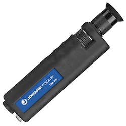
The first place to start when troubleshooting fiber optics is with the connector. To examine fiber optic connectors for cleanliness, according to the International Electrotechnical Commission (IEC) standard #61300-3-35, a fiber optic inspection microscope is utilized. (See Figure 1.)
The IEC standard verifies that four zones of a fiber optic connector or port are free of contaminants. These microscopes are designed to accommodate various fiber optic types, including single mode fiber (SMF), multiple mode fiber (MMF), and multiple-fiber push on (MPO) style connectors. They can be manual, using a mechanical focus dial, or automatic, utilizing a PC as a viewing screen with a USB scope adapter.
Since dirt can migrate, it’s crucial to ensure that the core, cladding, adhesive (epoxy), and contact (ferrule) zones of the fiber are free of contaminants. If any of the zones do not meet that requirement, it is essential to perform port cleaning. After cleaning, it is then necessary to re-examine the connector to confirm that it is free of contaminants or permanent damage.
Shockingly, improper cleaning methods can cause failure rates as high as 50% or more. That’s why fiber scoping and cleaning are an essential part of fiber optic maintenance.
2. Passive Optical Network (PON) Power Meter (PPM)
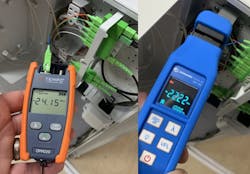
A passive optical network (PON) power meter (PPM) that’s specifically designed for testing and troubleshooting optical networks with multiple wavelengths. (See Figure 2.) A PPM is used to measure the optical power levels at various points in the fiber network, including at the optical line terminal (OLT), the optical network terminal/unit (ONx), and in the optical distribution network (ODN). These power meters typically measure optical power in units of decibels (dB) and can detect power levels as low as a few microwatts (μW). While a standard optical power meter (OPM) provides measurements at specific wavelengths, such as 1550 nm, the PPM is designed to test multiple wavelengths, including 1577 nm and 1490 nm, using wave division multiplexing (WDM) filters to separate and measure individual wavelengths.
They may also include additional features of a PPM, such as the ability to measure optical return loss (ORL) and the ability to perform automated tests for pass/fail analysis. PPMs are an essential tool for technicians to ensure the performance and reliability in PONs, as well as other fiber networks like remote PHY (R-PHY) or fiber deep networks. The latest PPM designs feature a pass-through port that allows an ONx to hear the OLT, enabling measurements to be conducted out of band (OOB) in both the upstream and downstream. Additionally, an attenuation by substitution test, which uses an optical light source (OLS) to generate a signal instead of the fiber optic equipment, is often used with PPM before activating operator equipment in the network. These tests are crucial in maintaining and troubleshooting fiber optic networks, making OPMs and PPMs an essential tool for fiber optic technicians.
“While there are many tools to troubleshoot fiber networks, it’s important to understand fiber fundamentals in order to use those tools to their fullest capabilities. If you’re a technician and/or engineer, consider enhancing your optical troubleshooting skills and knowledge by taking a certified course…”
3. Fiber Optic Visual Fault Locator (VFL)
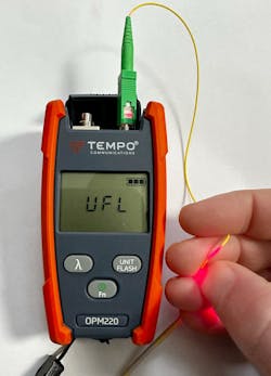
This troubleshooting tool is used by technicians to locate breaks, flawed splicing, or faults (e.g., macrobends) in a wide range of fiber optic cables. A VFL works by emitting a high-powered laser beam (e.g., 650 nm) that is directed into the fiber optic cable. (See Figure 3.) If there is a break or fault in the cable, the laser light will leak out and become visible at the point of the fault, allowing technicians to pinpoint the location of the problem. A VFL can save time and money by reducing the amount of time required to locate and repair faults. In addition, a VFL can help to improve network reliability by ensuring that faults are identified and repaired quickly, reducing downtime, and improving overall network performance. A technician can perform fiber identification by using different types of VFL pulses. Many other tools like OPMs and OTDRs have a VFL feature as well.
4. The Optical Time Domain Reflectometer (OTDR)
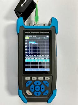
The OTDR is an extremely valuable troubleshooting testing instrument used to characterize the performance of a wide variety of fiber optic cables in a network. To ensure accurate measurements and overcome blind spots in OTDR testing, technicians typically use a launch cable, also known as a pulse width suppressor.
An OTDR works by sending a high-powered laser pulse into the fiber and measuring the amount of light that is reflected. By analyzing the reflected light, an OTDR can determine the length of the fiber, identify splice locations (e.g., fusion and mechanical), attenuation (loss), connectors, and locate any faults or breaks in the cable at the PHY layer. The OTDR software characterizes network anomalies as events and traces the fiber. (See Figure 4.) Distinguishing the events and traces allows a technician to quickly identify and repair problems, reducing downtime and improving network performance. Many OTDRs support automated testing capabilities, allowing technicians to perform tests quickly and easily without requiring advanced technical knowledge. Newer OTDRs feature data storage capabilities, allowing technicians to save, upload (e.g., cloud) and analyze test results over time, helping to identify trends and potential issues in the network.
Technicians may use an OTDR to launch a set pulse of laser light at a specific wavelength to detect anomalies in a fiber run. The pulse width, directly related to the pulse's optical power, can be adjusted to increase the dynamic range of the test, reducing the spatial resolution, or decrease it to increase spatial resolution but reduce the dynamic range. OTDR test results depend on the ODN topology being tested. For example, a centralized split FTTH topology will show a large attenuation event at the optical splitter. OTDRs are also useful for final acceptance testing of fiber cable reels and for validating wavelength continuity in WDM networks. Newer small form-factor pluggable (SFP) transceiver modules come with integrated micro OTDRs.
5. Optical Spectrum Analyzer (OSA)
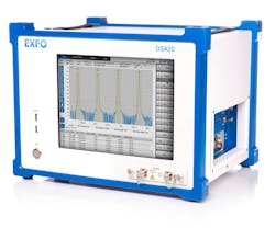
An OSA is a device used to measure the power and multiple wavelengths of light in a fiber optic system. (See Figure 5.) An OSA is not common for technicians, however facility and field engineers use OSAs to perform comprehensive measurements of the network. The OSA operates by separating the optical signal into its individual wavelength components and measuring the power at each wavelength. This information is then displayed on a high-resolution graph known as a spectrum. OSAs are capable of measuring the power and wavelength of light with high accuracy, making them an essential tool for characterizing, optimizing and troubleshooting fiber optic networks. Modern OSAs can perform automated measurements quickly and efficiently, allowing engineers to quickly identify and troubleshoot issues in the network. OSAs can be used with a variety of fiber optic components, such as amplifiers, filters, and multiplexers, making them a versatile tool for testing and troubleshooting fiber optic systems. Like OTDRs, many OSAs feature data storage capabilities, allowing engineers to save, upload and analyze test results over time, helping to identify trends and potential issues in the network.
To continuously monitor multiple fiber links, an operator's network assurance team may rack OSAs in the facility. Facility OSAs are capable of measuring wavelengths, optical signal power distribution, WDM, noise power characteristics, and optical signal to noise ratio (OSNR) measurements of light waves.
The OSNR is particularly useful for long-haul fiber optic networks that contain active components, such as amplifiers, which can add noise to a fiber link. It is defined as the ratio of the optical signal power to the noise power of the link. By performing an OSNR test, engineers can identify why an optical signal that falls within acceptable optical power levels is not being received. Additionally, OSNR tests can measure the Q-factor, which indicates the minimum signal-to-noise (S/N) ratio required for a specified bit error ratio (BER). Operators aim for a low BER that provides a high Q-factor and OSNR, indicating better receiver performance.
While there are many tools to troubleshoot fiber networks, it’s important to understand fiber fundamentals in order to use those tools to their fullest capabilities. If you’re a technician and/or engineer, consider enhancing your optical troubleshooting skills and knowledge by taking a certified course such as the SCTE Broadband Fiber Installer1 (BFI) program. It increases your employability, career advancement opportunities, earning potential and credibility in the rapidly growing field of fiber optic technology.
REFERENCES AND NOTES
1. SCTE Broadband Fiber Installer: https://www.scte.org/professional-certifications/become-certified/certification-exam-catalog/broadband-fiber-installer---online-exam/
About the Author
Steven R. Harris
Executive Director, Education and Technical Sales, L&D for SCTE
Steven R. Harris is an international technology speaker, educator, author, and thought leader who serves as Vice President, Global Market Development, for SCTE®, a subsidiary of CableLabs®. In this role, Steve is responsible for overseeing the architecture and evolution of education programs, professional credentialing, and customized career learning journeys, as well as international business development and partnerships for SCTE. For more information, email [email protected] or visit www.scte.org/BFI. Follow Steve on Twitter @stevenharrisnj. Follow SCTE on Twitter @scte, Facebook: https://www.facebook.com/TheSCTE, and LinkedIn: https://www.linkedin.com/company/scte/.
