Latest from FTTx/Optical Networks
Emerging Optical Testing Needs for Today and Tomorrow —
5G networks are expected to have speeds and bandwidth that match — or at least rival — wireline systems. To achieve that goal, fiber optics has moved into the fronthaul, as well as the central unit (CU). Optical test solutions that address these expanded verification requirements have now been developed to help optimize installation and operation of 5G networks, so they meet specified KPIs.
Fiber’s Expanding Role
When it comes to 5G transport, 3GPP is developing standards based on identifying different types of traffic and dividing it by application. Streaming video for entertainment, surfing the web, and similar, are given a lower priority. For mission-critical applications, including industrial Internet, Smart Grids, remote surgery, and intelligent transportation systems, Ultra-Reliable Low-Latency Communication (URLLC) is being used.
URLLC is part of GPP Release 15, and specifies 1 msec speed, which can only be attained with end-to-end latency. It is ideal for mission-critical applications because of its security and 99% reliability. Because of this, a different approach to system design and operations must be taken compared to 4G.
The physical layer is daunting because URLLC must satisfy both low latency and ultra-high reliability. This combination creates a considerably different type of quality of service (QoS) compared to traditional mobile broadband applications. Therefore, enhanced Mobile Broadband (eMBB) services are integrated into URLLC to establish one 5G air interface framework.
Open Standards for Agnostic Design
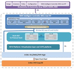
Mobile operators are driving an initiative to establish standards via the Open Radio Access Network Alliance (O-RAN) to evolve the fronthaul to satisfy the demands of 5G. O-RAN is an open standard designed to replace CPRI, which is a 4G specification developed by equipment manufacturers. Figure 1 shows the O-RAN architecture.
Figure 1. O-RAN architecture; courtesy of the O-RAN Alliance.
The O-RAN standard includes Open Fronthaul Specifications comprised of control, user, synchronization, and management plane protocols. User planes will treat traffic based on the O-RAN protocol, so all the network equipment will be compatible. Most operators and OEMs are committed to adopting the fronthaul specifications agreed to by the Alliance, and are introducing O-RAN-compliant products in commercial 5G networks.
IEEE also developed 2 transport network standards for 5G networks. 1914.1 is for architecture and divides the fronthaul into 2 Next Generation Fronthaul Interface (NGFI), or xhaul, elements to prioritize traffic. The standard splits traffic into the CU and remote unit (RU). The 5G base station is divided into 2 logical segments. The distributed unit (DU), which is not addressed in 1914.1, performs the heavy processing of the data. Once that is complete, the data is sent to the CU for transmission to the RU, with data given priority based upon use case and its mission-critical nature.
InvisiLight® Solution for Deploying Fiber
April 2, 2022Go to Market Faster. Speed up Network Deployment
April 2, 2022Episode 10: Fiber Optic Closure Specs Explained…
April 1, 2022Food for Thought from Our 2022 ICT Visionaries
April 1, 2022The other is IEEE 1914.3, which establishes the Radio of Ethernet (RoE) standard that specifies a transport protocol and encapsulation format for transporting time-sensitive wireless data between 2 endpoints over Ethernet-based transport networks. RoE was developed so networks can take the necessary evolution from CPRI to Ethernet. It is preferred over eCPRI, even though the latter provides a faster path for 5G deployment and utilization. eCPRI, however, has the same concerns as CPRI in that it is a specification developed by equipment manufacturers, not an open industry standard. IEEE 1914.3 will be compliant with the open O-RAN standard.
5G Network Design Considerations
These standards were developed to establish unified design processes for 5G networks. Among the biggest differences in network configuration is that the baseband unit will be software-driven in 5G, not hardware-driven as it is in 4G. It will also be situated closer to the radio than with legacy LTE networks. There is some consideration to having the baseband unit in the radio itself but given pricing pressures that option is not financially prudent. The DU will be further away in 5G than it was in current networks, as well. Often, it will be in the data center.
5G networks will also have a functional split whereby the radio is optimized by dividing the traffic based upon application. The actual partition is dependent on a few factors, including the location of the network. For example, in urban areas with countless small cells and where beamforming will be prevalent, low latency is the priority. Alternately, in networks placed near a major highway where connected cars will be traveling, high latency is necessary.
Optical Testing in 5G Networks
All these new standards and design considerations make verifying the performance of 5G networks a greater challenge. Testing takes on greater importance due to these variables, as well as the performance specifications associated with next-generation networks. Below are 5 important capabilities that field instruments must measure for 5G.
Bandwidth: With 4G, it was 10 Gbits/sec, but it will be 25 Gbits/sec per radio or sector with 5G. This will increase aggregate data transmitted and received to a tower by 10x compared to 4G. For this reason, field transport testers need to measure high data rates to support this added bandwidth capability. One solution, shown in Figure 2, should support 2×25 Gbits/sec in the field. Framing will also need to be supported by test tools, especially for 5G New Radio (5G NR), where eCPRI may be used.
Figure 2. Field transport testers need to support 2×25 Gbits/sec data rates to meet the needs of 5G.
Data splicing: The functional split by application of 5G adds another verification step field technicians must make on networks. The 4 defined xRAN profiles are C-plane, U-plane, S-plane and M-plane, which are used for transfer control, user data, synchronization, and management, respectively. Each of the xRAN planes has different QoS expectations over the NGFI-I network, which allows each Fronthaul Transport Node (FTN) to set the right priority across the network for every frame traversing the network. Field solutions need data splicing testing capability to accurately measure the difference between low and high latencies.
Packet-based testing: Given the 5G standards and protocols that will split and prioritize data transmissions based upon their mission-critical nature, packet-based testing is a priority. Most field technicians are not experienced in this area, so simple profiles must be integrated in the test solution. This means the right test tools should allow for duplicate testing in the field and for repeatable measurements that comply with 3GPP-based latency and timing thresholds.
Network synchronization: 4G networks are synched via cost-effective GPS, because LTE has favorable line of site. Due to network density and beamforming, GPS is not an option in 5G, which makes network synch measurements a new and important test. The solution is to rely on Ethernet and the Precision Time Protocol (PTP) grandmaster clock, as defined by the IEEE 1588, to distribute timing through the fiber to the nodes.
There are 2 challenges associated with this approach. As a signal transmits through each network element, the timing slips slightly. If there are too many elements, a timing error will occur. Phase error is another issue. Operators and network engineers need to determine the maximum amount of elements to ensure coverage but not adversely affect timing.
To address this issue, 2 profiles were developed. The PTP G.8275.2 enhanced profile meets the synchronization requirements of technologies such as LTE-TDD, LTE-A CoMP, and LTE-MBSFN. The G.8275.1 profile is also used in networks where phase or time-of-day synchronization is required and where each network device participates in the PTP protocol.
Because a boundary clock is used at every node in the chain between PTP grandmaster clock and PTP slave elements, there is a reduction in time error accumulation through the network.
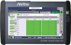
Test solutions must measure the element threshold based upon these standards or performance issues, including dropped calls and outages, will eventually occur. Many of these problems will not directly point to poor synchronization, which makes troubleshooting long, expensive, and frustrating. Therefore, field technicians need a PPT-aware test solution that can connect to the grandmaster clock to determine the nodes that are causing slips and fails. To conduct the most accurate timing error analysis, the test solution should be able to measure timing error within +/-20 m/secs. Figure 3 provides a display of IEEE 1588 v2 (PTP) clock status real time information.
Figure 3. A display of a test solution supporting IEEE 1588 v2 (PTP) clock status real time information.
eCPRI/IEEE1914.3 (RoE): For time and cost efficiencies, both eCPRI and RoE measurements should be made with a single instrument. Some test solutions have a dual-port 25G eCPRI/RoE function to optimize testing by offering efficient signal generation and analysis plus precision one-way latency measurement of transport networks. This provides support for implementing URLLC.
Like this Article?
Subscribe to ISE magazine and start receiving your FREE monthly copy today!
Conclusion
5G networks pose multiple new design elements and standards to achieve the latency, speed, and bandwidth, expected by the next-generation network, as well as meet the needs of many mission-critical use cases. Because of this, transport testing has become more robust and complicated. Field test tools must address the standards and measurement requirements in a simple and efficient manner for optimal deployment, installation, and operation, of 5G networks to achieve KPIs.


