Latest from FTTx/Optical Networks
Aerial Fiber Cable Type Installation Options and Considerations —
The right cable choice and efficient plant design are critical to deploy cables that meet the high levels demanded by future services to Data Centers, FTTH, Cell Towers, 5G, enterprise commercial, and Inter-city links. This article focuses on 2 traditional aerial cable installations methods: lashed fiber cable to steel messenger, and All Dielectric Self Support (ADSS) cable.
Cable Types
Most cable manufacturers offer an assortment of cables for the Outside Plant (OSP) including ADSS and Loose Tube or Ribbon cable designs for direct buried, duct, and aerial lashed installations. ADSS is usually a loose tube design that have fiber counts up to 432, and are designed for aerial spans without use of a steel messenger. These cables have a robust design that allows them to hold themselves up with attachments at each pole without introducing mechanical strain into the glass fibers.
Suppliers have several different strengths of ADSS cables to choose from, with selection by the user primarily based on parameters of span length, installation sag, and environmental loads the cable will experience over its lifetime. Although for short-length installations, ADSS cables can also be installed in duct, lashed on a steel messenger, or direct buried, their intended application is in self-support span. Standard loose tube and ribbon cables designed for OSP require support by a steel messenger wire to which the cable is lashed when installed aerially. (It should be mentioned that there are also OSP cables available that have a steel messenger wire attached when made in the factory, but these are less commonly deployed and are not discussed in this article.)
In essence, it is important to select the right cable type and installation method for the intended application:
• ADSS — aerial installation without need of a steel messenger.
• Typical OSP Cables — aerial installations requiring the use of a steel messenger for support along the span.
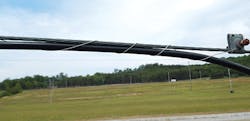
Figure 1. Cable Lashed to Steel Messenger
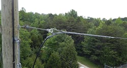
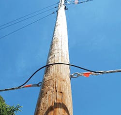
Figure 4. ADSS Dead End
Identify Goals of the Project’s Fiber Installation
There are 2 basic network designs to choose from:
1. Point-to-Point: express fibers with no need for access along the route. Typically used for a long-haul, town-to-town or city-to-city links, and in rural applications where access points for the fibers are very far apart. Pole spacings are usually 250 feet to 300 feet.
2. Point-to-Multipoint: fiber distribution typically at every pole with pole spacing usually between 100 feet to 150 feet apart. Typically used for dense urban and suburban environments where frequent access points for fiber are needed.
It is also helpful to understand the installation infrastructure to select the correct cable:
• Can the cable be installed in the power space, and is there room on the poles and along the messenger (sometimes called a strand) for terminals, closures, and slack coils?
• Is there an existing messenger that the new cable can be over-lashed to?
• Can a new messenger be installed? Is there space and permission to attach?
Installing the correct cable based on the installation needs is critical in achieving the goals of the project. As an example, it is counterproductive to install a cable that is expressed past the customers that want to purchase services provided by the very fibers being expressed. The same holds true for installing a cable best suited for a local distribution design and using it for a point-to-point long-haul application. The idea is to use the available infrastructure and pathways with the correct cable design to achieve design objectives.
InvisiLight® Solution for Deploying Fiber
April 2, 2022Go to Market Faster. Speed up Network Deployment
April 2, 2022Episode 10: Fiber Optic Closure Specs Explained…
April 1, 2022Food for Thought from Our 2022 ICT Visionaries
April 1, 2022Aerial Cable Selection
The following are important criteria to consider when making decisions on which cable to select and deploy. Let’s examine them by application.
Point-to-Point: In large High Voltage Structures (Transmission Towers), ADSS should be placed out of the of electrical potential zone created by the 3 power phases so there are no induced currents on the cable jacket.
In poles with Distribution Voltages, use the power space to install ADSS cable. This depends on the details of the design, of course. the spans can be upwards of 2,000 feet before a dead-end is needed. The National Electrical Safety Code (NESC) has information on correct installation in the power space.
Point-to-Multi-Point: Poles with or without power distribution typically use standard OSP cables that are lashed to steel messengers within the communication space.
ADSS: The best applications for ADSS cable types are on high voltage transmission towers or in the power space on joint-use pole runs for a point-to-point application:
The advantages of using ADSS include:
• There is no metal in the cable. Therefore, no bonding and grounding is required.
• No steel messenger is required; the cable supports itself.
• Existing pathways on pole runs and transmission towers can be utilized. No new poles are required, and cables can be installed up to about 2,000 ft. before being dead ended.
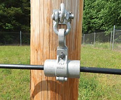
Figure 5. ADSS Tangent Support
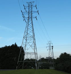
Figure 7. High Tension Transmission Towers
The top 5 disadvantages and limitations in using ADSS include:
• If used in a point-to-multipoint application, the cable must dead end at every pole that requires a terminal, closure, or slack loop.
• Cost of ADSS cable is generally 3X or more than that of standard OSP aerial cable. This will offset some savings owing to the elimination of requiring that a new messenger being installed.
• New line or drop cable needed for future services could not be attached to an ADSS cable, thereby limiting the flexibility to over-lash another cable, plus restrictions on drop installations which cannot be attached to the ADSS then spanned to the customer residence. The drop will need to be spanned from the terminal which may be too far, or require another terminal be installed close to the house.
• Securing a closure, terminal, or snow shoe to the cable is not possible with ADSS, for example a taught sheath closure for unplanned splice points is not an option.
• Specific installation parameters, such as initial installation sag, span length, loading on the cable, assumed wind/ice loadings, etc. are used to determine the particular ADSS cable used. In the event that there is a field change or weather event that exceeds those parameters used to specify the cable, this can cause a service outage.
Figure 6. ADSS – Dead End to Pole
Lashed OSP Cable: This is the best application choice when used in a point-to-multipoint architecture.
The top 5 advantages of using lashed OSP cable include:
• Much higher fiber counts than ADSS cables when using ribbon type cable., and available with armor or all-dielectric designs.
• Drops and cables can be over-lashed to existing cables that are lashed to a messenger.
• The messenger provides some protection to the cable against falling tree branches,
• Taut sheath access is possible when unforeseen access is required, also terminals, standard closures, and snow shoes can be attached to the messenger.
• Cables can be installed continuously with slack access loops left at poles to allow for terminals to be added by a mid-span access to the cable.
The overlashing process, if available, helps alleviate clearance and loading issues, helping to simplify the make-ready process otherwise associated with the addition of new attachments on poles, with regard to meeting NESC requirements.
Figure 2. Typical Lashing Operation
The top disadvantages and limitations in using lashed OSP cable include:
• A new messenger may need to be installed if over-lashing is not an option.
• Bonding and grounding are required on the messenger and armor cable.
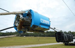
Figure 3. Cable lasher equipment
And the Winner Is… ?
If the objective is to install fiber between 2 points, ADSS is a good choice if pathways on transmission towers or within the power space on a pole run are available. This approach would be found most often in rural or inter-city applications.
If the objective is point-to-multipoint for urban and suburban fiber distribution, the lashed OSP cable is the best solution allowing for use of many access terminals and for general installation flexibility.
Service provisioning for businesses and homes by their nature need to be served by flexible plant and have entry points where fibers can be readily accessed to be extended to the customer. In aerial deployments, the lashed cable design allows for the goals of flexible plant and ease of access for quick service order completions.
Urban and suburban areas are usually in a state of constant change (churn) with new buildings, customer service alterations, renovations, zoning changes, business growth, etc., creating the need for flexible fiber cable facilities. With the goals of flexibility to address growth and churn, quick service delivery, and easy fiber access, lashed aerial cable is should be used to build the infrastructure that can allow this to happen.
Lashed aerial cable allows for terminal installation either at the pole or on the steel messenger all being in the communication space well below the power space as per the NESC. Access in this space is permitted by communications technicians who are not necessarily trained in high voltage work.
Additionally, cable slack required to lower a splice closure to ground level for access is possible with lashed aerial plant with the use of snow shoes attached to the messenger wire.
When lashed cable is compared to ADSS cable, the cost of installing a messenger (when necessary) is to a large degree offset with the additional cost of ADSS cable. In many cases over-lashing is possible. Hardware and equipment to install are virtually equivalent and fiber reliability is the same in either type cable.
ADSS has definite advantages for point-to-point designs, and lashed aerial cable has advantages when used in point-to-multipoint architectures.
Remember that the total cost of the plant needs to be considered. That means not only the upfront capital costs of cable, messenger, attachment hardware and closures, but also the installation and operational cost associated with placing the facilities and ready access for initial customer service turn-up and long-term maintenance.
Like this Article?
Subscribe to ISE magazine and start receiving your FREE monthly copy today!
NESC Workshop
To learn more about the National Electrical Safety Code, you can attend the "NESC Workshop: Next Code, Next Generation", October 2, 2019 – October 3, 2019, in Kansas City, Missouri. This NESC workshop presents a unique opportunity for the NESC community to hear initial Subcommittee recommendations on key change proposals, and to solicit the necessary public input in order to determine the content of the 2022 NESC. For more information, please visit https://standards.ieee.org/events/nesc-workshop-october-2019.html.

Ernie Gallo | Director at Network Infrastructure Solutions, a division of Ericsson, Inc.,
Ernie Gallo is Director at Network Infrastructure Solutions, a division of Ericsson, Inc., and an IEEE C2 National Electrical Safety Code - Committee Member, Subcommittees SC2, SC4, SC5, and SC8. He has more than 40 years of experience in outside plant products, requirements, deployment, and electrical safety codes and standards such as the NEC and NESC. For more information, please email [email protected] or visit https://www.ericsson.com/en. Follow Ericsson on Twitter @ericsson.
For more information, please visit https://standards.ieee.org/products-programs/nesc/ to learn more information about the NESC and NESC Products. Follow the IEEE SA on Twitter @IEEESA. We welcome you to contribute to our efforts by joining the NESC.


