Latest from FTTx/Optical Networks
Leveraging ADSS Cable Technology —
Electric utilities, including both private and publicly owned energy providers as well as cooperatives (co-ops), have a rich history of deploying fiber networks for both internal use with SCADA or traditional Ethernet systems.
Today, electric utilities are realizing the potential for additional revenue streams with a vast customer base in rural America without access to reliable, high-speed broadband. With this large underserved subscriber base and complete ownership of the right-of-ways (utility poles), building FTTx networks easily, efficiently, and inexpensively, is possible more than ever thanks to emerging, as well as existing, field-proven technologies.
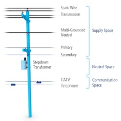
That’s why they are utilizing their existing right-of-way (RoW) to install dark fiber and then lease to a variety of customers. Utilizing the space below the neutral, the key to these deployments is running fiber cables in the supply zone or neutral space, above the communications space to prevent clashing of cables. (See Figure 1.)
Figure 1. NESC Joint Use Pole Diagram
To support these types of installations, fiber optic cable manufacturers designed all-dielectric self-supporting cable which, as its name implies, can span pole to pole without the need for a messenger wire. Due to the dielectric construction of the cable, installers don’t have to worry about overhead lines inducing a charge to any metallic cable components, thus removing safety concerns without the need for grounding. Flat drop cables can self-support as well, but typically at much shorter distances than their more robust ADSS cable counterparts which can span over 1,500 feet between poles depending on the cable design.
Optical ground wire (OPGW) is another cable technology used in the utility space where it is placed in the topmost position on the support structure as a shield wire while also providing a telecommunications path via fibers internal to the cable structure. Transmission lines utilize a shield/ground/earth wire to "shield" conductors from lightning strikes, so OPGW allows utilities to provide data transmission as well as shield wire capability with the same cable.
It’s All About Scale
As service providers are increasing investment in fiber infrastructures and discontinuing antiquated copper-based content and data delivery, FTTx installations continue to scale. As a result, lower drop installation methods particularly involving fusion splicing have proven difficult for service providers relative to keeping up with demand. Thus, pre-terminated hardened multiport terminals have become increasingly popular in FTTx deployments over the past several years.
Factory terminated hardened fiber optic connectors (HFOCs) allow for quicker drop installations than previous methods while maintaining a sealed interface between the drop and terminal. This promotes long-term reliability when installed anywhere in the network: underground, in pedestals, on poles, on aerial strand, or on ADSS cables. The terminal is stubbed with a preconfigured length of cable that is run to a splice closure where the terminal is spliced into the F2 cable. This removes the need to repeatedly access a closure containing F2 fibers to install drops, which is advantageous versus traditional closure terminal options, especially in regard to express fibers serving additional terminals downstream.
InvisiLight® Solution for Deploying Fiber
April 2, 2022Go to Market Faster. Speed up Network Deployment
April 2, 2022Episode 10: Fiber Optic Closure Specs Explained…
April 1, 2022Food for Thought from Our 2022 ICT Visionaries
April 1, 2022Historically, pre-terminated hardened access multiports have utilized a flat drop cable design. As most of these multiport terminals are 12 ports or fewer, the flat drop design is a cost-effective way to package the required fibers while remaining robust and low-profile, for underground duct or direct bury as well as aerial lashed deployments. The cable design is also able to be self-supported in aerial applications using simple 2-pair drop wire wedge clamps previously used only for copper twisted pair drops.
Self-support capability comes from the dual fiberglass-reinforced plastic strength members as well as extra fiber length (EFL) contained within the gel-filled buffer tube. EFL ensures that as the cable experiences strain due to environmental loading conditions such as ice and wind, strain on the fiber is kept near zero to avoid introducing attenuation or affecting long-term mechanical reliability. (See Figure 2.)
Figure 2. Flat Drop Cable Max Span Length at 1% Sag
While self-support capability of flat drop cable adds flexibility to designing pre-terminated multiport terminals into FTTx networks, its primary functionality comes into play for single-fiber drops spanning from the terminal to the customer premise. These spans are often much shorter than spans seen in the distribution space.
In cases of longer-than-recommended spans, single-fiber drop cables are often one of the lowest cost pieces of material in the network, and are viewed as replaceable in the event of a rare heavy ice storm.
Leveraging the Right Solutions
When attempting to use flat drop cables in a self-support capacity for multiport terminal tails, it is important not to exceed the recommended span lengths for the cable. Environmental loading beyond recommended span lengths could cause temporary outages of multiple customers connected to that terminal, or even fiber breaks requiring costly repairs or complete replacement of the multiport.
In NESC light loading zones, exceeding the recommended max span would be very rare in most distribution pole spans. However, in NESC medium or heavy loading zones, exceeding the 275’ or 150’ respective max spans could be much more frequent, especially in rural locations.
In order to meet the longer span length requirements at NESC medium or heavy loading in rural locations, utilities could run strand wire and lash flat drop multiport tails. This method is not preferable as metal strand is not suited for the supply space due to the conductive nature of the strand, and the communications space is often reserved for leased customers such as Telco and CATV providers.
Another option is to utilize multiports that have an ADSS tail option, such as AFL’s TITAN RTD® multiport terminals. These terminals utilize a miniaturized ADSS cable which, due to the stranded buffer tube core and aramid yarn strength members, allow for much longer span lengths typical to rural environments, even at NESC medium or heavy loading. (See Figure 3.)
Figure 3. TITAN ADSS Cable Max Span Length at 1% Sag
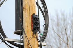
While ADSS is advantageous to use as a multiport terminal stub because this cable type can be run in the supply or neutral zone on the utility pole, it is unlikely utilities would desire the multiport terminal itself be mounted in the supply zone. Mounting the terminal in the supply zone could be troublesome as only certified installers would have access, which could increase costs. In these instances, it is recommended to bring the multiport terminal further down the pole, even below the communications attachment points. This allows for access by most telecom contractors using only a ladder rather than a bucket truck. (See Figure 4.)
Figure 4. Hardened Pre-Terminated Multiport Terminal
In closing, electric utilities are in a unique position to help rural Americans who do not have adequate access to broadband. Utilities own and can leverage their rights-of-ways (utility poles) to build FTTx networks while creating additional revenue streams for the future. To do that, they must employ field-proven techniques and solutions that are scalable, cost-efficient, and field-installation friendly.


