Latest from FTTx/Optical Networks
3 Life-Saving Guidelines for Fiber:
With the latest advances in optical high-performance networks, connectors are becoming ever more crucial components in passive fiber optic infrastructure. High-quality connectors ensure optimum transmission rates and constant network availability in all areas, from WAN to metropolitan area and campus networks, as well as backbone networks and subscriber connections. A reliable data network is in everyone’s best interests in order to keep on top of the growing demand for data transfer.
They cannot do their job if they have even the smallest bit of dirt on them. Why is dirt so bad? Dirt, along with damage such as scratches and cavities, is one of the main causes of 3 problems related to return loss:
Problem #1. change in the refractive index
Problem #2. pathway to the air
Problem #3. backscattering of the modes or photons
The effects of dirt on insertion loss are slightly less serious. Water residue, dust, or other residues, are typically pushed to the outside by the convex shape of the connector endface. Therefore, it’s unlikely that larger particles will remain in the core area. At the edges, they can deflect only a small portion of the light. Even slightly deflected modes can still be coupled into the next fiber. (See Figure 1.)
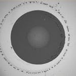
Figure 1. How optical fiber contact surfaces look in different states. From left to right: cleaned connection, water residue, dust and dirt particles, and a fingerprint. Swiss fiber optic specialist R&M recommends that, before pairing, you should always first check fiber optic connections and then clean if necessary.
So, now that you know how bad dirt can be, use these 3 guidelines to keep your fiber alive and kicking:
Guideline #1
Know when to clean
It is becoming increasingly important to test all connectors and adapters, and, if necessary, to clean them before they are mated. In this case, both sides of a connection including the guide sleeve should be cleaned, as recommended in IEC 62627-01/TR. This applies to devices and test cables, as well as for network components.
New connectors should also be tested and, if necessary, cleaned. This is the best guarantee for a reliable optical network. In fact, various studies have shown that up to 85% of local faults are caused by connectors that either have not been cleaned carefully or have not been cleaned at all.
Interestingly, it is a popular misconception that every connector should always be cleaned before being plugged in. Most connectors actually arrive at their place of deployment in the pristine state in which they left the production facility. In such cases, the installer can actually only make the quality worse by cleaning the connector. The rule should not be "always clean before you plug in" but in fact be "always check before you clean".
Guideline #2
Check surfaces
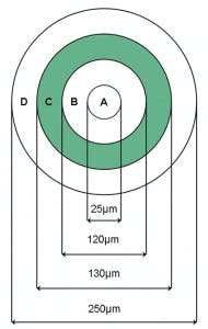
Although the manufacturer will conduct a test using an interferometer, it is still necessary to perform a visual inspection on site using a microscope or another suitable tool. Here, the surfaces of the fiber ends are checked for scratches, cavities, adhesive residue, and dirt. In order to achieve the defined optical properties of the connector, all 4 zones of the end surface of the fiber (as shown in Figure 2) must be completely free of dirt. Otherwise, the following criteria apply:
Figure 2. Surface zones on the end of the fiber.
Zone A: No scratches or pits permitted. 25 µm is 3 times the core diameter. Therefore, the zone must be checked especially carefully.
Zone B to C: Small scratches and cavities may be permitted. Here, too, absolutely no dirt must be present.
Zone D: Although this is already the ferrule region, this zone must still be checked as it is also part of the transmission area due to the contact stress on the connector. The interferometry test also registers a diameter of 250 µm.
The detailed pass/fail criteria are standardized in IEC 61300-3-35.
Guideline #3
Know HOW to clean properly
The following tools are recommended for cleaning: lint-free cloths, isopropyl alcohol, lint-free cotton buds, and dry cleaning tape.
To clean, wet a lint-free cloth with a few drops of isopropyl alcohol.
Clean the ferrule cladding with the wet part of the cloth. The first 3 to 5 mm are the most important here, as this part is fed into the guide sleeve depending on the connector type.
Lay the cloth out on a table or flat surface. The surface should not be too hard. Several cloths placed on top of one another can be used here. This makes a small cushion.
Pull the connector in a straight line across the wet part of the cloth. Do this very gently. Pull the connector from the wet part of the cloth over to the dry part. The alcohol dissolves dirt and oil residues, and is removed when the connector is pulled across the dry part of the cloth.
Various cleaning devices are available on the market. With most of these, the connector does not move across the cloth, but instead the cloth moves under the connector. However, in principle, the procedure is the same as described earlier.
The procedure for inspecting and cleaning optical connections is described precisely in Annex B of IEC 62627-01/TR/Ed2 – Fiber optic interconnecting devices and passive components – Technical Report – Fiber optic connector cleaning methods. This technical report stresses how important it is to use the correct procedure.
IEC 62627-01/TR comprehensively describes the cleaning methods for fiber endfaces. Furthermore, all suppliers of optical components and systems should provide cleaning instructions for their products that are specifically tailored to the material properties and design features.
Figure 3.
Figure 4.
Figure 5.
Figure 6.
Figure 7.
Figure 8.
Figure 9.
Figure 10.
Figure 11.
Save
Save
Save
Save
Save
Save
Save
Save
Save
Save
Save
Save
Save


